
Method for calculating convexity conversion relationship between work roll and support roll of four-high mill

A calculation method and a technology for converting relationships, applied in the field of metallurgy, can solve problems such as complex wave shape, plate shape deterioration, and inability to improve plate shape, so as to achieve the effect of ensuring consistency and improving accuracy and quality

Inactive Publication Date: 2016-09-28
TANGSHAN DELONG STEEL CO LTD
View PDF7 Cites 0 Cited by
  • Summary
  • Abstract
  • Description
  • Claims
  • Application Information

AI Technical Summary

Problems solved by technology

For four-roll rolling, when designing the roll, the work roll is often ground into a crown roll [3] , which can effectively offset the small deformation of the work rolls and backup rolls during the rolling process. However, for the four-roll mill with the function of work roll shifting, because the rolling mill has the function of roll shifting, the work rolls during the rolling process Roll shifting is often required, and the resulting shifting of the crown of the work roll makes the roll gap form a special shape. This shape is more complicated, and the compound wave in the edge can be controlled by cooperating with the bending roll. [4] , but sometimes such a complicated roll gap shape not only fails to improve the shape of the plate, but also adds complex wave shape, which deteriorates the shape of the plate

Method used


Image

  • Method for calculating convexity conversion relationship between work roll and support roll of four-high mill
  • Method for calculating convexity conversion relationship between work roll and support roll of four-high mill
  • Method for calculating convexity conversion relationship between work roll and support roll of four-high mill

Examples


Embodiment Construction

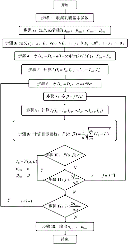
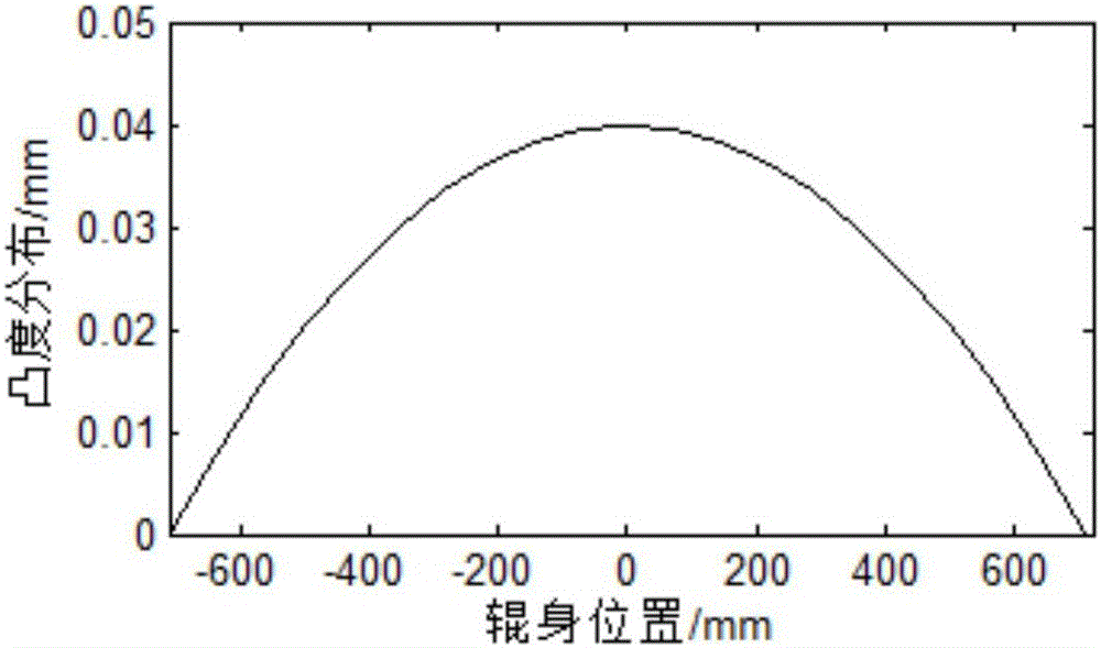
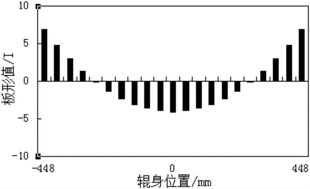
[0027] Taking a four-high rolling mill as an example, the calculation method of the crown conversion relationship between the work roll and the backup roll of the four-high rolling mill is further explained. The calculation process is as follows figure 1 Shown:

[0028] First, in step (a), the basic parameters of the rolls are collected: mainly including the body length L of the work rolls w =1420mm, length L of the roller body of the support roller b =1380mm, the nominal roll diameter D of the work roll w =449.5mm, the nominal roll diameter D of the support roll b =1099.8mm;

[0029] Subsequently, in step (b), the maximum crown coefficient α of the support roller is defined and given max =4、Maximum opening degree coefficient β max =0.5, define the optimal crown coefficient α of the support roller best , Optimum opening coefficient β best ;

[0030] Subsequently, in step (c), the objective function F is defined 0 , support roller crown coefficient α, opening degree co...


PUM


Abstract

The invention discloses a method for calculating convexity conversion relationship between a work roll and a support roll of a four-high mill. The method mainly comprises the following calculation steps: 1, collecting basic parameters of rolls; 2, defining a maximum convexity coefficient, a maximum opening degree coefficient, an optimum convexity coefficient and an optimum opening degree coefficient of the support roll; 3, defining a target function and initializing the target function; 4, calculating export plate shape value distribution under specific conditions of convexity and opening degree coefficients of the work roll; 5, calculating export plate shape value distribution when the work roll is a flat roll and the support roll is in a corresponding roll shape; 6, calculating the target function; and 7, obtaining the optimum convexity coefficient and the optimum opening degree coefficient of the support roll. According to the method disclosed in the invention, the convexity conversion between the work roll and the support roll can be calculated, so that the consistency of the strip outlet plate shapes is ensured to the greatest extent, the problem that the work rolls with convexity alternates to generate complicated roll cleaning so as to make the plate shape worse under certain specific conditions is solved, and the precision and quality of plate rolling under certain specific conditions are improved.

Description

technical field [0001] The invention belongs to the technical field of metallurgy, in particular to a strip steel cold rolling production process. Background technique [0002] There will be slight deformation of the roll during rolling. In order to control the cross-sectional thickness distribution of the rolled material, there are two methods that can be used: (1) Apply roll bending force to offset the roll deformation during rolling through the pre-deformation of the work roll or intermediate roll. amount of deformation [1] . (2) Give the work roll or backup roll a convexity, and offset the micro-deformation of the roll during the rolling process through the convexity of the roll itself [2] . For four-roll rolling, when designing the roll, the work roll is often ground into a crown roll [3] , which can effectively offset the small deformation of the work rolls and backup rolls during the rolling process. However, for the four-high mill with the function of work roll s...

Claims


Application Information

Patent Timeline
IPC IPC(8): G06F19/00
CPCG16Z99/00
Inventor 白振华兴百宪张君钱承刘亚星崔亚亚杜江城
Owner TANGSHAN DELONG STEEL CO LTD
Learn More