Multilayer ceramic capacitor and method for manufacturing the same
A technology of ceramic capacitors and ceramics, which is applied in the direction of laminated capacitors, capacitors, fixed capacitors, etc., can solve problems such as cracks, lower reliability of internal electrodes and external electrodes, and achieve good solderability, high-efficiency manufacturing, and connection reliability. high effect
- Summary
- Abstract
- Description
- Claims
- Application Information
AI Technical Summary
Problems solved by technology
Method used
Image

Examples
experiment example 1
[0087] In order to confirm the importance of the multilayer ceramic capacitor of this embodiment, samples of sample numbers 1 to 10 in Table 1 were prepared using a conductive paste containing Cu powder as a conductive component and Sn added ( multilayer ceramic capacitors).
[0088] In addition, the detailed specifications of the conductive paste are as follows.
[0089] The amount of solid content: 25vol%
[0090] Ratio of Cu powder in solid content: 70vol%
[0091] Ratio of glass in solid content: 25vol%
[0092] Ratio of Sn in solid content: 5vol%
[0093] Particle size of Cu powder: 3μm
[0094] Glass particle size: 2μm
[0095] Composition of glass: BaO-SrO-B 2 o 3 -SiO 2 Glass-like frit (glass frit is converted into oxide, BaO: 10% by weight to 50% by weight, B 2 o 3 : 3% to 30% by weight, SiO 2 : 3% to 30% by weight glass)
[0096] In addition, when preparing the samples of sample numbers 1 to 10 in Table 1, the conductive paste was applied to the first end...
experiment example 2
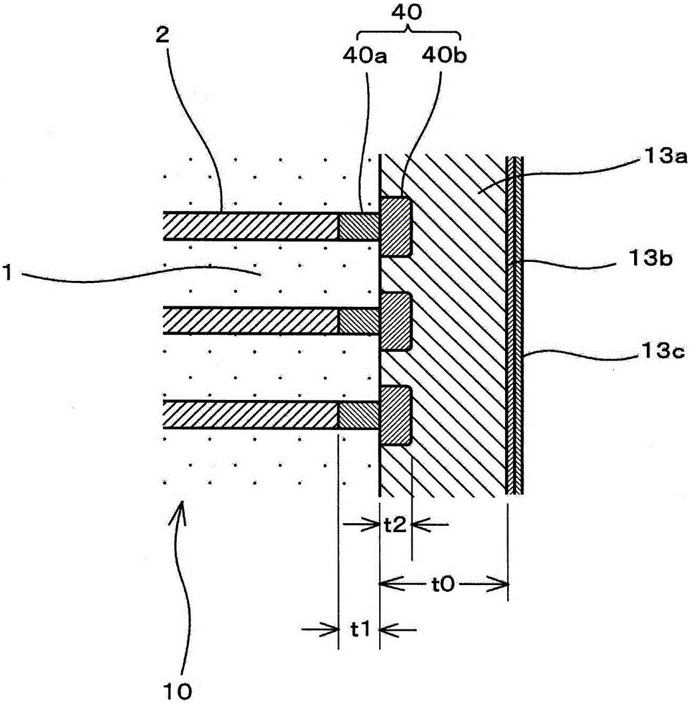
[0129] In addition, in addition to setting the thickness of the external electrode main body to 40 μm, setting the thickness of the interdiffusion layer on the external electrode side to 10% of the thickness of the external electrode main body, and setting the thickness of the interdiffusion layer on the internal electrode side to 0.2 μm to 7 μm Samples of sample numbers 11 to 15 in Table 2 were produced in the same manner as in the case of the samples of Experimental Example 1 (samples in Table 1) described above, except that the samples were changed within the range of .
[0130] Furthermore, a test for checking the number of crack occurrences and a 0Ω discharge test were implemented for each of the produced samples.
[0131] In addition, the number of occurrences of cracks was checked by grinding the samples (multilayer ceramic capacitors) from the side (the end face of the ceramic body on which the external electrodes were formed) including the surface in the thickness dire...
PUM
| Property | Measurement | Unit |
|---|---|---|
| Thickness | aaaaa | aaaaa |
| Particle size | aaaaa | aaaaa |
| Thickness | aaaaa | aaaaa |
Abstract
Description
Claims
Application Information
 - Generate Ideas
- Intellectual Property
- Life Sciences
- Materials
- Tech Scout
- Unparalleled Data Quality
- Higher Quality Content
- 60% Fewer Hallucinations
Browse by: Latest US Patents, China's latest patents, Technical Efficacy Thesaurus, Application Domain, Technology Topic, Popular Technical Reports.
© 2025 PatSnap. All rights reserved.Legal|Privacy policy|Modern Slavery Act Transparency Statement|Sitemap|About US| Contact US: help@patsnap.com