Element pin measurement machine and measurement process thereof

A measuring machine and measuring mechanism technology, applied in the direction of electrical components, electrical components, etc., can solve problems affecting the automatic assembly process of the shell, component height or installation position error, component skew, etc.

Active Publication Date: 2016-09-28
SHENZHEN XING GRAIN AUTOMATION CO LTD
View PDF3 Cites 12 Cited by
  • Summary
  • Abstract
  • Description
  • Claims
  • Application Information

AI Technical Summary

Problems solved by technology

[0002] In recent years, the electronics industry has developed rapidly. With the improvement of computer hardware, the improvement of software and the emergence of various APPs, the functions and types of electronic products are developing in a diversified direction. PCB boards are the hardware carriers of electronic products. It integrates various The circuit function module is the basis for the realization of the function of electronic products. There are many kinds of electronic components welded on the PCB. The component feet and pinholes are connected by soldering. For the latter case, since the diameter of the pinhole is larger than the diameter of the component feet, the components will be skewed when connecting, or other conditions that occur in actual production will eventually lead to the PCB on the back of the board. Component feet or component height or installation position errors on the front of the PCB board will affect the automatic assembly process of the subsequent electronic product shell. Therefore, a component foot measuring device is needed to detect and measure the component feet, component height and position on the PCB board. , to pick out defective products to ensure the normal operation of the entire automated assembly line

Method used


Image

  • Element pin measurement machine and measurement process thereof
  • Element pin measurement machine and measurement process thereof
  • Element pin measurement machine and measurement process thereof

Examples


Embodiment Construction

[0059] The present invention will be further described below in conjunction with accompanying drawing:

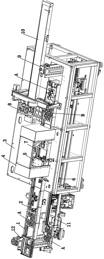
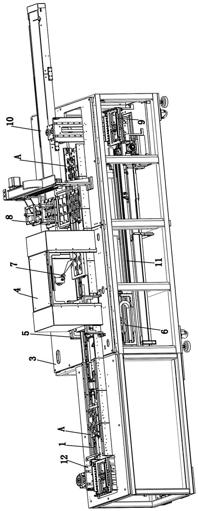
[0060] Such as Figure 1 to Figure 16 As shown, the technical solution adopted by the present invention is as follows: a component foot measuring machine, comprising an upper material belt 1, a frame 3, a lower measuring mechanism 6, an upper measuring mechanism 7, a product handling mechanism 8, a discharge belt 10, and a jig lifting Mechanism and lower layer material belt 11, wherein, above-mentioned upper layer material belt 1 and lower layer material belt 11 are arranged on the top and the bottom of frame 3 respectively, and pass through frame 3 and extend to both sides, and moving direction is opposite; Above-mentioned jig lifts The mechanism includes a front jig lifting mechanism 12 and a rear jig lifting mechanism 9 respectively arranged at the front end and tail end of the upper layer material belt 1 and the lower layer material belt 11. The jig A drives the product...


PUM


Abstract

The invention discloses an element pin measurement machine and a measurement process thereof. The e element pin measurement machine comprises an upper-layer material band, a frame lower measurement mechanism, an upper measurement mechanism, a product carrying mechanism, a discharging band, a tool elevating mechanism and a lower-layer material band, wherein the upper-layer material band and the lower-layer material band are respectively disposed above and below a frame; the tool elevating mechanism comprises a front tool elevating mechanism and a rear tool elevating mechanism, a tool drives a product to transmit the product backwards via the upper-layer material band to the lower measurement mechanism and the upper measurement mechanism for element pin and element measurement; and the product carrying mechanism is arranged above the rear end of the upper-layer material band, the product measurement mechanism carries the product after measurement to a discharging band at the side portion of the upper-layer material band, the product is discharged via the discharging band, the empty tool flows into the rear elevating mechanism, the rear elevating mechanism drives the tool to descend and pushes the tool into the lower-layer material band, the tool flows back to the front elevating mechanism along with the lower-layer material band, is driven to ascend via the front elevating mechanism, and slides into the upper-layer material band, and thus through cyclic flow, the product is continuously automatically conveyed.

Description

technical field [0001] The invention relates to the field of mechanical automation, in particular to a component foot measuring machine and a measuring process thereof. Background technique [0002] In recent years, the electronics industry has developed rapidly. With the improvement of computer hardware, the improvement of software and the emergence of various APPs, the functions and types of electronic products are developing in a diversified direction. PCB boards are the hardware carriers of electronic products. It integrates various The circuit function module is the basis for the realization of the function of electronic products. There are many kinds of electronic components welded on the PCB. The component feet and pinholes are connected by soldering. For the latter case, since the diameter of the pinhole is larger than the diameter of the component feet, the components will be skewed when connecting, or other conditions that occur in actual production will eventually...

Claims


Application Information

Patent Timeline
Patent Type & Authority Applications(China)
IPC IPC(8): H05K13/08
CPCH05K13/08
Inventor 宾兴覃凤瑞谢深君
Owner SHENZHEN XING GRAIN AUTOMATION CO LTD
Why Eureka
Try Eureka