Structure for front part of vehicle body

A technology for the front and structure of the vehicle body, which is applied to the lower structure, upper structure, vehicle components, etc., can solve the problem of increasing the weight of the vehicle body, and achieve the effect of suppressing deformation and improving protection performance.

Active Publication Date: 2016-09-28
HONDA MOTOR CO LTD
View PDF11 Cites 19 Cited by
  • Summary
  • Abstract
  • Description
  • Claims
  • Application Information

AI Technical Summary

Problems solved by technology

In order to sufficiently absorb the collision energy, the left and right mounting brackets for connecting the subframe need to be large, and the weight of the vehicle body will increase.
Furthermore, the vehicle body front structure known in the above-mentioned Patent Document 5 is a structure that can be applied only when the left and right mounting brackets for connecting the subframe are provided.

Method used


Image

  • Structure for front part of vehicle body
  • Structure for front part of vehicle body
  • Structure for front part of vehicle body

Examples


Embodiment

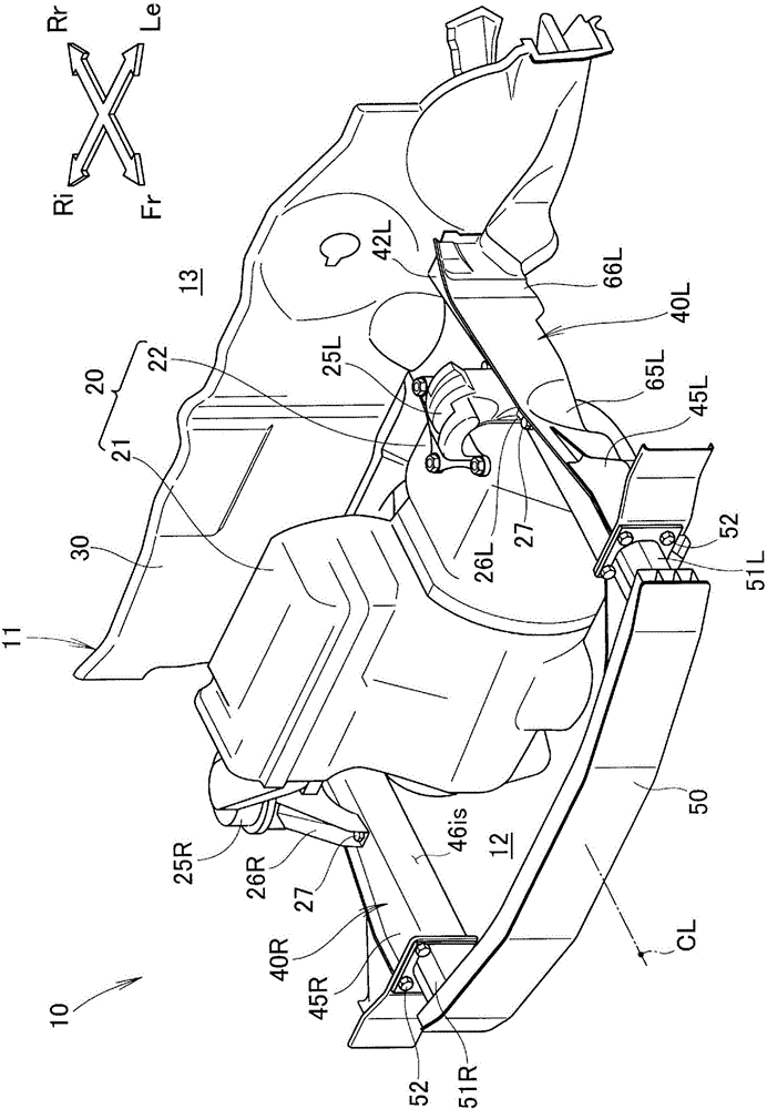
[0052] The vehicle body front structure of the embodiment will be described. Such as figure 1 and figure 2 As shown, vehicle 10 is, for example, a passenger car. A power unit compartment 12 at the front and a vehicle compartment 13 located directly behind the power unit compartment 12 are formed inside a vehicle body 11 of the vehicle 10 .

[0053] A power unit 20 is housed in the power unit chamber 12 . The power unit 20 is a so-called transverse type power unit in which an engine 21 and a transmission 22 are arranged in the vehicle width direction and combined with each other.

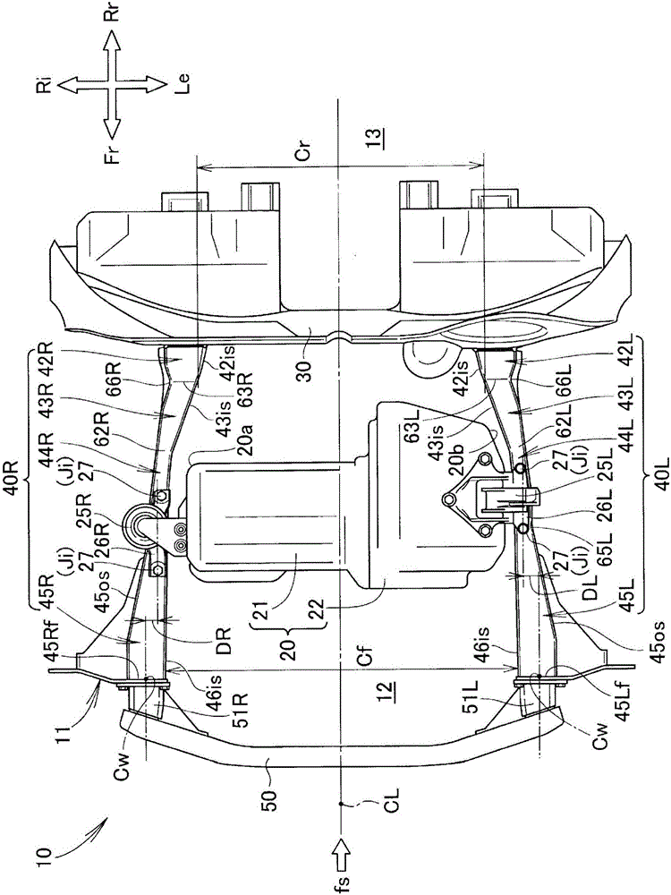
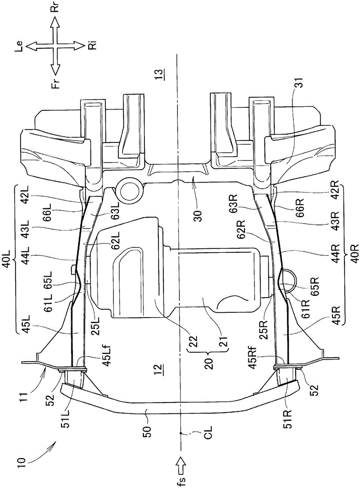
[0054] Such as Figure 1 to Figure 4 As shown, the vehicle body 11 is constituted by a monocoque body, and is formed in a left-right symmetrical shape with respect to a vehicle width centerline CL passing through the center of the vehicle 10 in the vehicle width direction and extending in the vehicle front-rear direction. The front portion of the vehicle body 11 includes a dashboard lower panel...


PUM


Abstract

A structure for the front part of a vehicle body includes left and right front side frames (40L, 40R) provided with at least left and right front bending sections (61L, 61R), left and right intermediate bending sections (62L, 62R), and left and right rear bending sections (63L, 63R). Due to a collision load (fs) applied to the front end of the vehicle body (11), the left and right front bending sections (61L, 61R) bend so as to protrude inward in the width direction of the vehicle and thereby grasp and restrain a power unit (20) from both sides in the width direction of the vehicle. The left and right intermediate bending sections (62L, 62R) are located at a distance rearward from the left and right front bending sections (61L, 61R). The left and right rear bending sections (63L, 63R) are located at a distance rearward from the left and right intermediate bending sections (62L, 62R), bend outward in the width direction of the vehicle due to the collision load (fs), and absorb collision energy when subjected to a collision with the power unit (20) which moves backward together with the left and right front bending sections (61L, 61R) due to the collision load (fs).

Description

technical field [0001] The present invention relates to a vehicle body front structure in which left and right front side frames capable of mounting a power unit are improved. Background technique [0002] Common vehicles such as automobiles have left and right front side frames at the front of the vehicle body. The left and right front side frames extend from the lower panel of the dashboard toward the front of the vehicle body, and can mount a power unit such as an engine unit. [0003] The left and right front side frames can be plastically deformed by a collision load (frontal collision load) acting on the front end of the vehicle body from the front. At this time, the power unit moves toward the rear of the vehicle body and touches the lower panel of the instrument panel. In contrast, it is desired to improve the performance of protecting occupants located in the vehicle interior behind the dashboard lower panel. In order to improve the protection performance for the...

Claims


Application Information

Patent Timeline
Patent Type & Authority Applications(China)
IPC IPC(8): B62D21/15B62D25/20
CPCB62D21/152B60K5/04B60K5/1216B60R19/26B60Y2306/01B62D25/082B62D25/14
Inventor 宫本裕贵安井健樋口英生河村惠里
Owner HONDA MOTOR CO LTD
Why Eureka
Try Eureka