Pipeline leakage monitoring method and device

A pipeline leakage and monitoring device technology, applied in pipeline systems, mechanical equipment, gas/liquid distribution and storage, etc., can solve the problem of not being able to know the exact location of the leakage point on the pipeline

Active Publication Date: 2016-10-05
PETROCHINA CO LTD
View PDF4 Cites 22 Cited by
  • Summary
  • Abstract
  • Description
  • Claims
  • Application Information

AI Technical Summary

Problems solved by technology

[0004] However, the current transmission pipeline monitoring technology cannot know the exact location of the leakage point on the transmission pipeline

Method used


Image

  • Pipeline leakage monitoring method and device
  • Pipeline leakage monitoring method and device
  • Pipeline leakage monitoring method and device

Examples


Embodiment Construction

[0033] In order to make the purpose, technical solutions and advantages of the embodiments of the present invention clearer, the technical solutions in the embodiments of the present invention will be clearly and completely described below in conjunction with the drawings in the embodiments of the present invention. Obviously, the described embodiments It is a part of embodiments of the present invention, but not all embodiments. Based on the embodiments of the present invention, all other embodiments obtained by persons of ordinary skill in the art without creative efforts fall within the protection scope of the present invention.

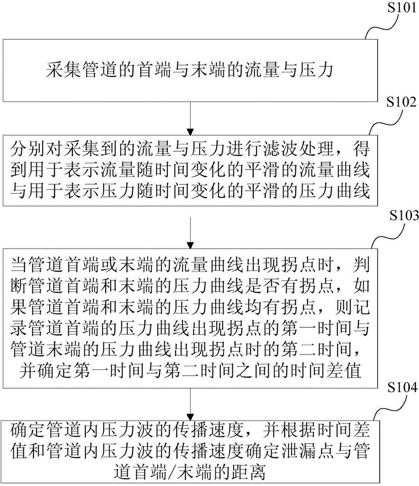
[0034] figure 1 It is a schematic flowchart of the pipeline leakage monitoring method provided in Embodiment 1 of the present invention. Such as figure 1 As shown, the pipeline leakage monitoring method provided in this embodiment includes:

[0035] S101. Collect the flow and pressure at the head end and the end of the pipeline.

[0036] Speci...


PUM


Abstract

The invention provides a pipeline leakage monitoring method and device. The pipeline leakage monitoring method provided by the present invention includes: collecting the flow and pressure at the head end and the end of the pipeline; when an inflection point appears on the flow curve at the head end or the end of the pipeline, judging whether the pressure curve at the head end or the end of the pipeline is There is an inflection point, if the pressure curves at the head end and the end of the pipeline have inflection points, record the time between the first time when the inflection point appears in the pressure curve at the head end of the pipeline and the second time when the inflection point occurs in the pressure curve at the end of the pipeline and determine the distance between the leak point and the beginning of the pipeline or the distance between the leak point and the end of the pipeline according to the time difference and the propagation velocity of the liquid pressure wave in the pipeline. The invention can realize the accurate positioning of the leakage point on the pipeline by using the change of the flow at both ends of the pipeline and the time difference of the inflection point of the pressure curve.

Description

technical field [0001] The invention relates to oil pipeline technology, in particular to a pipeline leakage monitoring method and device. Background technique [0002] When oil or natural gas is collected and transported in the oil field, it is difficult to rely on manual management due to the long pipeline route. However, natural damage or man-made damage will cause pipeline perforation or fracture. If it cannot be detected and treated in time, it will not only affect production, but also lead to a series of adverse consequences such as a large amount of oil leakage and environmental pollution, resulting in huge economic losses. Therefore, it is necessary to monitor whether there is leakage in the oil and gas pipeline. [0003] At present, the existing oil field pipeline monitoring technology is to install flowmeters or pressure sensors at both ends of the pipeline. The flowmeter or pressure sensor at both ends detects the change of flow or pressure value, and sends out ...

Claims


Application Information

Patent Timeline
Patent Type & Authority Applications(China)
IPC IPC(8): F17D5/02
Inventor 程世东魏小林张春涛操红梅李丽樊晨黄天虎邱奇李明江邱亮张彬田殿龙白晓红
Owner PETROCHINA CO LTD
Why Eureka
Try Eureka