
Pre-wetting device for automatic ultrasonic detection

A technology of ultrasonic testing and pre-humidifier, which is applied in the direction of material analysis, instruments, and measuring devices using sonic/ultrasonic/infrasonic waves, which can solve inaccurate testing results, affect ultrasonic testing results, and affect equipment testing accuracy and service life. problems, to ensure the coupling effect, prolong the service life, and improve the detection accuracy.

Inactive Publication Date: 2016-10-05
SHANGHAI JINYI INSPECTION TECH
View PDF2 Cites 1 Cited by
  • Summary
  • Abstract
  • Description
  • Claims
  • Application Information

AI Technical Summary

Problems solved by technology

[0002] The automatic ultrasonic flaw detection equipment used to detect shafts, rods, pipes, etc. is an expensive, high-precision mechatronic equipment, which has strict requirements on the surface state of the inspected workpiece. In actual production, the surface of the inspected workpiece There are often a large amount of impurities such as iron oxide scale attached, which will seriously affect the ultrasonic detection effect, and indirectly affect the detection accuracy and service life of the equipment; at the same time, conventional ultrasonic detection must use water or engine oil as a coupling agent
How to ensure sufficient and stable couplant on the surface of the inspected workpiece is the key to the effective implementation of automatic ultrasonic testing. Once the coupling is insufficient or unstable, the test results will be inaccurate, and in severe cases, automatic ultrasonic testing cannot even be implemented.

Method used


Image

  • Pre-wetting device for automatic ultrasonic detection
  • Pre-wetting device for automatic ultrasonic detection
  • Pre-wetting device for automatic ultrasonic detection

Examples


Embodiment Construction

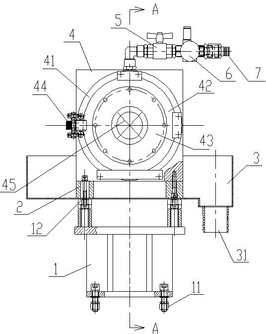
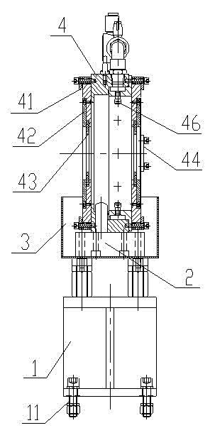
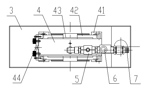
[0018] Example figure 1 , figure 2 with image 3 As shown, the pre-humidifier for automatic ultrasonic detection of the present invention includes a base 1, a bottom plate 2, a collection tank 3, a box body 4, an annular pressure plate 41, an annular sealing plate 42, a scraper plate 43, a stop valve 5, and a fluid control valve. 6. Quick connector 7 and several nozzles 46, the collection tank 3 is arranged on the top surface of the base 1, the bottom plate 2 is located in the collection tank 3 and fixed to the bottom plate 2 and the collection tank 3 by bolts The top surface of the base 1, the box body 4 is arranged on the top surface of the bottom plate 2 through bolts, the bottom surface of the box body 4 is open and communicates with the collection tank 3, and the top surface, the front and the back of the box body 4 are respectively provided with Through holes, the through holes on the top surface of the box body 4 are sequentially connected to the shut-off valve 5, th...


PUM


Abstract

The invention discloses a pre-wetting device for automatic ultrasonic detection. A collecting tank of the pre-wetting device is arranged on the top face of a base, a bottom plate is located in the collecting tank, and bolts penetrate through the bottom plate and the collecting tank to fix the bottom plate to the top face of the base. A box is arranged on the top face of the bottom plate through bolts, an opening is formed in the bottom face of the box and communicated with the collecting tank, through holes are formed in the top face, the front face and the back face of the box respectively, the through hole in the top face of the box is connected with a stop valve, a fluid control valve and a quick connector in sequence through a pipeline, an annular pressing plate, an annular sealing plate and a scraping plate are arranged in the through holes in the front face and the back face of the box respectively in sequence, an annular channel coaxial with the through holes in the front face and the back face of the box is formed in the box, a plurality of nozzles are arranged on the inner ring of the annular channel at intervals, and the input ends of the nozzles are communicated with the pipeline connected with the through hole in the top face of the box. The pre-wetting device can effectively scrap off impurities on the surface of a workpiece, prevent foreign matter from entering precise detection equipment and prolong the service life of the detection equipment; the pre-wetting device can pre-wet the detected workpiece, guarantee the coupling effect and improve detection precision.

Description

technical field [0001] The present invention relates to a pre-humidifier for automatic ultrasonic testing. Background technique [0002] The automatic ultrasonic flaw detection equipment used to detect shafts, rods, pipes, etc. is an expensive, high-precision mechatronic equipment, which has strict requirements on the surface state of the inspected workpiece. In actual production, the surface of the inspected workpiece There are often a large amount of impurities such as iron oxide scale attached, which will seriously affect the ultrasonic testing effect, and indirectly affect the testing accuracy and service life of the equipment; at the same time, conventional ultrasonic testing must use media such as water or engine oil as a coupling agent. How to ensure that there is sufficient and stable couplant on the surface of the inspected workpiece is the key to the effective implementation of automatic ultrasonic testing. Once the coupling is insufficient or unstable, the test re...

Claims


Application Information

Patent Timeline
Patent Type & Authority Applications(China)
IPC IPC(8): G01N29/22G01N29/28
Inventor 张义凤许荣
Owner SHANGHAI JINYI INSPECTION TECH
Learn More