Safe lifting platform

A lifting platform and platform technology, applied in the direction of operating tables, tables with variable table heights, medical science, etc., can solve problems such as table damage, safety hazards, and low product safety, so as to improve accuracy, safety, avoid damaging effects

Inactive Publication Date: 2016-10-12
ZHEJIANG JIECHANG LINEAR MOTION TECH
View PDF5 Cites 24 Cited by
  • Summary
  • Abstract
  • Description
  • Claims
  • Application Information

AI Technical Summary

Problems solved by technology

[0002] At present, although the lifting devices on the market have solved the problem of being able to lift, but when the load of the lifting device is running under any load within the overload, when the platform it is connected to hits the window sill, writing cabinet, children playing, etc., it cannot To respond quickly, you must respond when the load reaches the specified value. At this time, the table may be damaged, and the child may encounter a safety accident. Therefore, the safety of this product is not high, and there are potential safety hazards

Method used


Image

  • Safe lifting platform
  • Safe lifting platform
  • Safe lifting platform

Examples


Embodiment 2

[0045] The difference between this embodiment and the first embodiment is that a buffering component is provided between the triggering component and the motor.

[0046] Such as Figure 5 , 6 As shown, a buffer 9 is provided between the triggering member 7 and the surface of the motor 4. The buffer 9 is a soft rubber pad, specifically a silicone pad, and the buffer 9 is fixed to the surface of the motor 4 by pasting.

[0047] The advantage of this embodiment is that by providing a buffer between the triggering member and the surface of the motor, when the triggering member is subject to a large collision, the sensing element is guaranteed not to be damaged, and the service life of the sensing element is increased.

[0048] It can be understood that the cushioning member is a rubber pad or a foam pad or a sponge pad or a spring.

[0049] It is understandable that the buffer member is fixed to the lower surface of the trigger member by pasting.

[0050] It can be understood that the buffe...

Embodiment 3

[0052] The difference between this embodiment and the first embodiment is that the triggering component is installed in a different way.

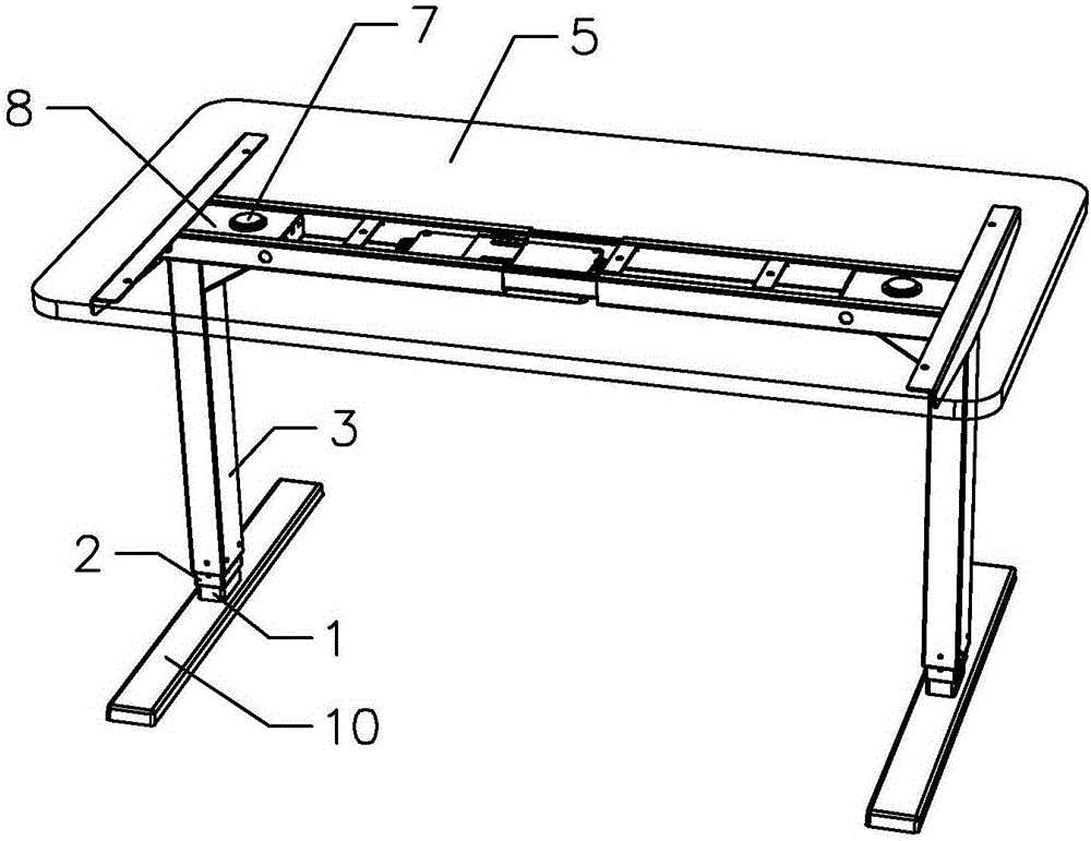
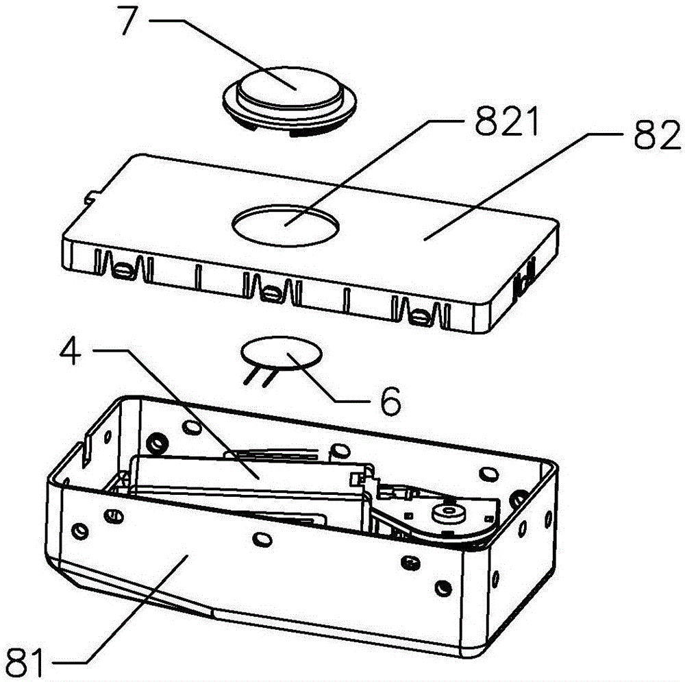
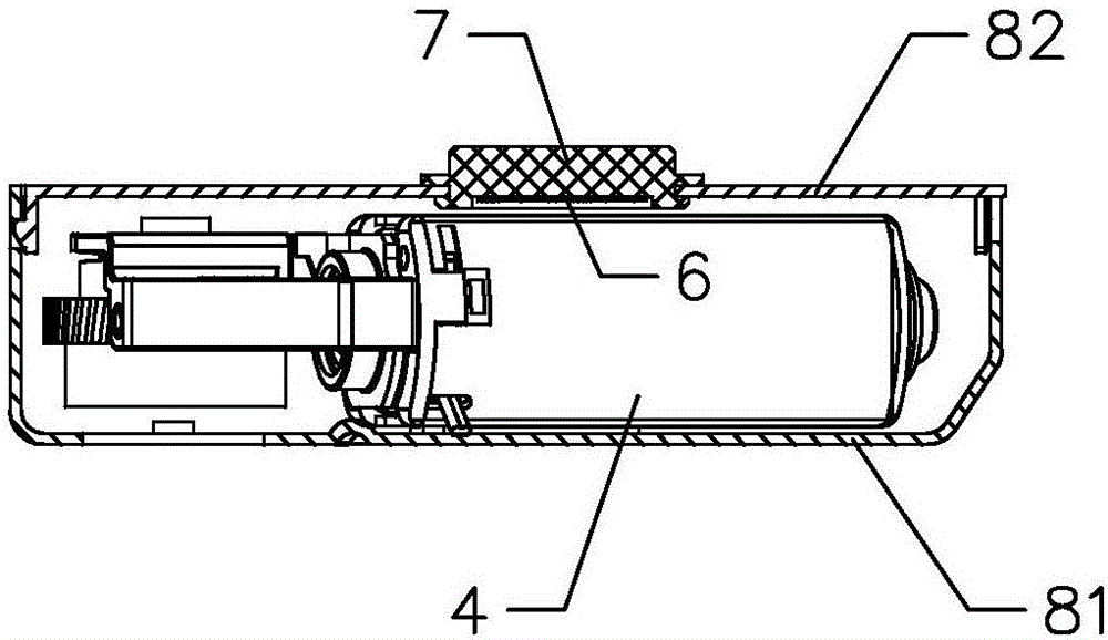
[0053] Such as Figure 7 , 8 As shown, the trigger 7 is attached to the upper surface of the cover 82, the sensing element 6 is provided on the lower surface of the cover 82 corresponding to the trigger 7, and the trigger 7 is fixed to the upper surface of the cover 82 by pasting.

[0054] The advantage of this embodiment is that it facilitates the installation of the trigger and the sensing element, and improves the sensitivity of the trigger and the sensing element, thereby improving the accuracy of detection; at the same time, the trigger is fixed on the upper surface of the cover by pasting, Easy to install and fix and reliable.

[0055] It is understandable that there is a buffer between the sensing element and the motor, and the buffer is a silicone pad, a rubber pad, a foam pad, a sponge pad, or a spring.

Embodiment 4

[0057] The difference between this embodiment and the first embodiment is that the trigger is different.

[0058] In this embodiment, the trigger 7 and the cover 82 of the support shell 8 are integrally formed, the sensing element 6 is attached to the lower surface of the cover 82, the sensing element 6 is fixed to the lower surface of the cover 82 by pasting, and the sensing element 6 passes The deformation of the cover 82 is used to detect whether the platform collides, so as to realize the anti-collision function of the lifting platform.

[0059] The advantage of this embodiment is that by integrally forming the trigger part and the cover plate, the parts of the lifting platform are reduced, the cost is reduced, the processing and assembly are reduced, and the production efficiency is improved.

[0060] It is understandable that there is a buffer between the sensing element and the motor, and the buffer is a silicone pad, a rubber pad, a foam pad, a sponge pad, or a spring.


PUM


Abstract

The invention provides a safe lifting platform, comprising a lifting column, a motor driving the lifting column to move, a platform connected to the lifting column, a control panel electrically connected to the motor, a safety protection device is provided between the platform and the lifting column, and the safety protection The device includes an inductive element and a trigger that causes the inductive element to generate a safety signal when the platform collides. The inductive element is electrically connected to a control board, and the control board receives the safety signal from the inductive element and controls the motor to stop or reverse rotation. By installing a safety protection device between the platform and the lifting column, the sensitivity of the platform under the action of external force is improved, and the accuracy of the detection of the safety protection device is further improved; at the same time, the safety during the lifting process is improved, and platform collision is avoided. It can protect the safety of people when they are damaged by obstacles, or even when people hit the platform.

Description

Technical field [0001] The invention relates to a lifting device, in particular to a safe lifting platform. Background technique [0002] At present, although the lifting device on the market solves the problem of lifting, when the lifting device load is running at any load within the overload, when the platform connected to it touches a window sill, a writing cabinet, a child playing, etc., it cannot Respond quickly, and you must respond when the load reaches the specified value. At this time, the table may have been damaged and the child has encountered a safety accident. Therefore, the safety of the product is not high and there is a safety hazard. Summary of the invention [0003] The purpose of the present invention is to provide a safe lifting platform. [0004] In order to achieve the above objective, the present invention adopts the following technical solutions: a safe lifting platform, comprising a lifting column, a motor driving the lifting column, a platform connected t...

Claims


Application Information

Patent Timeline
Patent Type & Authority Applications(China)
IPC IPC(8): A47B9/20A61G13/02A61G13/10A61G7/018
CPCA47B9/20A47B2200/0051A47B2200/0057A47B2200/0062A47B2200/008A61G7/018A61G13/02A61G13/10
Inventor 陆小健陈雪莉张东行谭宇辰陈永斌
Owner ZHEJIANG JIECHANG LINEAR MOTION TECH
Why Eureka
Try Eureka