Novel electromechanical washing device

A cleaning device, electromechanical technology, applied in the direction of lighting devices, lighting devices, circuit layout, etc., can solve the problems of inability to achieve cleaning effect, inconvenience, increase cleaning time costs and labor costs, etc., to improve the performance and scope of application, fully The effect of cleaning operations

Inactive Publication Date: 2016-10-12
CHENGDU KECHUANG JIASI TECH
View PDF6 Cites 23 Cited by
  • Summary
  • Abstract
  • Description
  • Claims
  • Application Information

AI Technical Summary

Problems solved by technology

However, for existing cleaning devices, due to structural and design constraints, the positional relationship between the parts to be cleaned and the cleaning nozzles placed therein is often fixed, which makes the cleaning nozzles often only To clean part of the surface of the parts to be cleaned, the position of the parts to be cleaned needs to be changed frequently during the cleaning process, which not only greatly increases the time cost and labor cost of cleaning, but also fails to achieve a sufficient and thorough cleaning effect; in addition, when After cleaning, the parts to be cleaned often need to be dried in another drying device, which also causes great inconvenience, and all of the above greatly reduce the performance and scope of application of the cleaning device

Method used


Image

  • Novel electromechanical washing device

Examples


Embodiment Construction

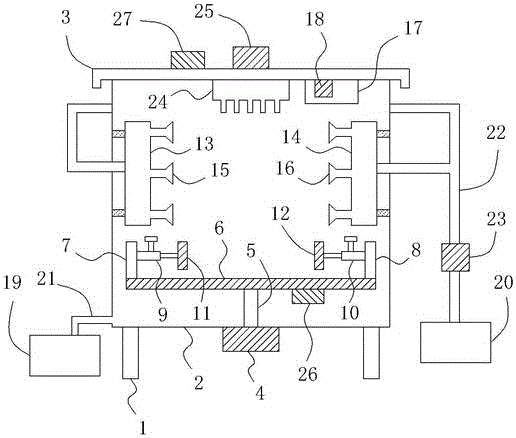
[0013] like figure 1 As shown, a novel electromechanical cleaning device comprises a support 1 and a casing 2 located on the support 1, a casing cover 3 is provided on the top of the casing 2, a motor 4 is provided below the casing 2, and a motor 4 is arranged on the bottom of the casing 2. A rotating shaft 5 is connected to the output shaft end of the rotating shaft 5, and the rotating shaft 5 is arranged vertically upwards and extends into the inside of the box body 2. At the same time, a horizontally arranged tray 6 is connected to the top of the rotating shaft 5, and a plurality of trays are uniformly arranged on the tray 6. Through holes (not shown in the figure), the left and right baffles 7 and 8 are vertically arranged at the left and right ends of the tray 6 respectively, and the left telescopic rod 9 is arranged on the right side of the left baffle 7, and the right baffle The left side of plate 8 is provided with right telescopic link 10, is respectively provided wit...


PUM


Abstract

The invention relates to a novel electromechanical washing device which comprises a bracket, a box body and a box cover, wherein a motor is arranged below the box body, and is connected with a rotating shaft; the top end of the rotating shaft is connected with a tray; a left baffle plate and a right baffle plate are arranged at the left end and the right end of the tray; a left expansion rod and a right expansion rod are respectively arranged at the right side of the left baffle plate and the left side of the right baffle plate; a left clamping plate and a right clamping plate are respectively arranged at the right end of the left expansion rod and the left end of the right expansion rod; a left spray pipe and a right spray pipe are respectively arranged at the left end and the right end in the box body; a plurality of left spray heads and right spray heads are arranged on the left spray pipe and the right spray pipe; a transparent cover body is arranged at the bottom end of the box cover; a camera, a microcontroller and a wireless emitter are arranged in the transparent cover body; a sewage box is arranged at the left of the box body; a water purifying box is arranged at the right of the box body; a drainage port of the box body is connected with the sewage box through a drainage pipe; the water purifying box is connected with the left spray pipe and the right spray pipe through a water discharge pipe; and a pump body is arranged on the water discharge pipe. With the adoption of the structure, washing operation can be carried out more conveniently, quickly and sufficiently, and drying treatment can be conducted effectively after washing.

Description

technical field [0001] The invention relates to a novel electromechanical cleaning device. Background technique [0002] In the process of mechanical production and processing, it is often necessary to clean various mechanical parts or mechanical equipment, so cleaning devices are used accordingly. However, for existing cleaning devices, due to structural and design constraints, the positional relationship between the parts to be cleaned and the cleaning nozzles placed therein is often fixed, which makes the cleaning nozzles often only To clean part of the surface of the parts to be cleaned, the position of the parts to be cleaned needs to be changed frequently during the cleaning process, which not only greatly increases the time cost and labor cost of cleaning, but also fails to achieve a sufficient and thorough cleaning effect; in addition, when After cleaning, the parts to be cleaned often need to be placed in a drying device for drying, which also causes great inconven...

Claims


Application Information

Patent Timeline
Patent Type & Authority Applications(China)
IPC IPC(8): B08B3/02F26B21/00F21V23/04F21V33/00F21Y115/10
CPCB08B3/022F21V23/0442F21V33/00F26B21/004
Inventor 缪家戌
Owner CHENGDU KECHUANG JIASI TECH
Why Eureka
Try Eureka