Chamfering machine

A chamfering machine and chamfering technology, applied in the field of chamfering machines, can solve the problems of long time-consuming, batch processing of unfavorable materials, and low chamfering efficiency

Active Publication Date: 2016-10-12
东莞市晋诚机械有限公司
View PDF12 Cites 17 Cited by
  • Summary
  • Abstract
  • Description
  • Claims
  • Application Information

AI Technical Summary

Problems solved by technology

With this kind of processing equipment, due to structural limitations, it is generally necessary to re-clamp the material after one end of the material is chamfered to complete the chamfering of the other end of the material, and manual loa

Method used


Image

  • Chamfering machine
  • Chamfering machine
  • Chamfering machine

Examples


Embodiment Construction

[0027] In order to facilitate the understanding of those skilled in the art, the present invention will be further described below in conjunction with the embodiments and accompanying drawings, and the contents mentioned in the embodiments are not intended to limit the present invention.

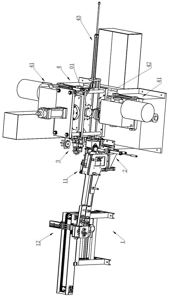
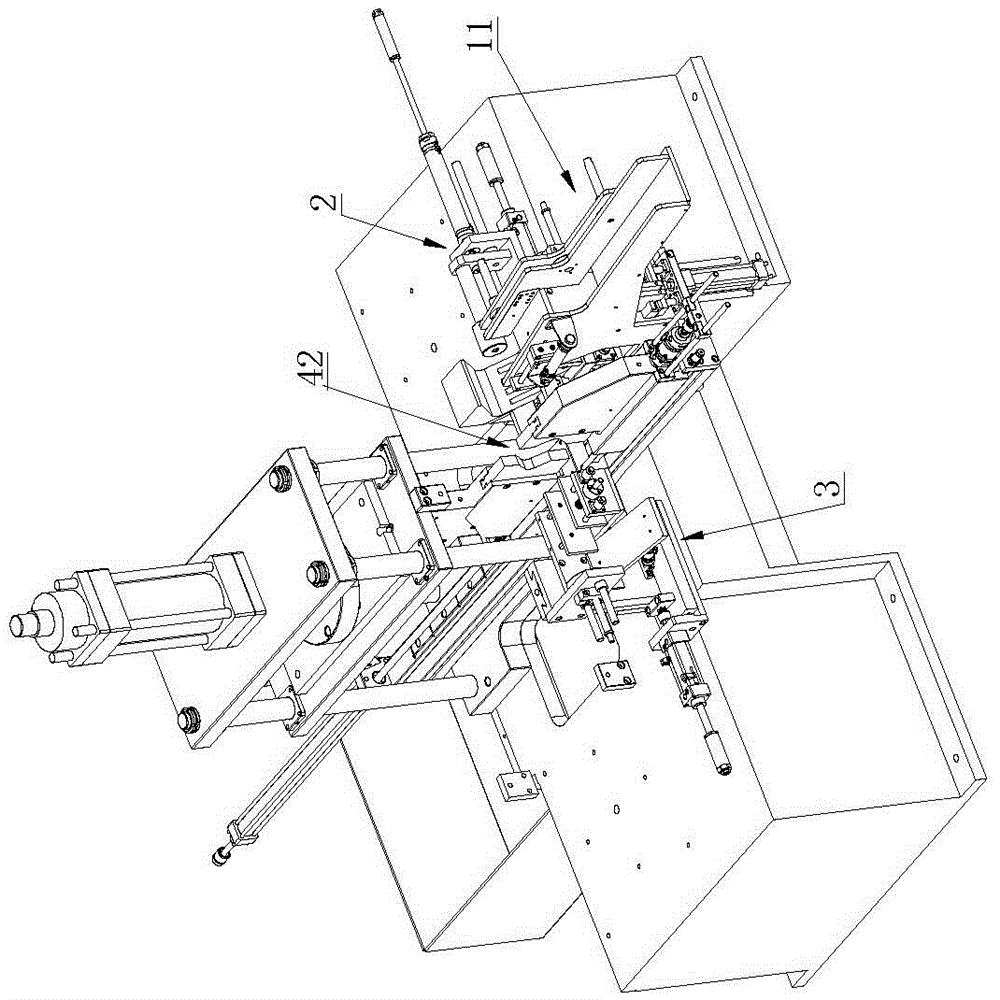
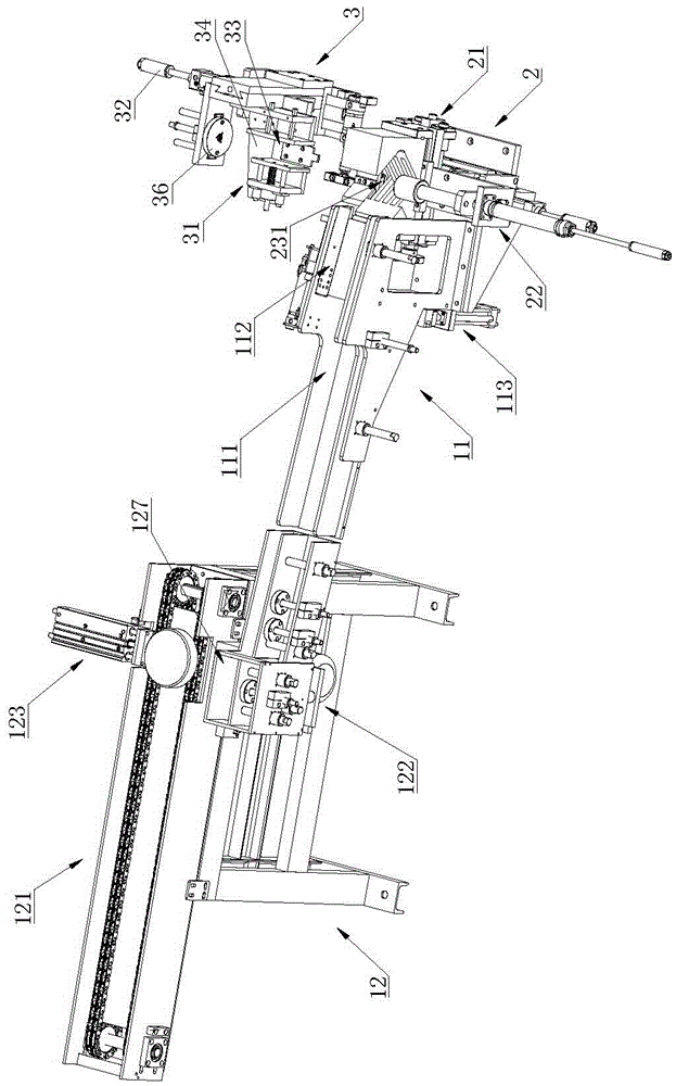
[0028] Such as Figure 1 to Figure 10 Shown, a kind of chamfering machine comprises feeding device 1, is arranged on the push-out device 2 of feeding device 1 outlet, is arranged on the unloading device 3 of push-out device 2 side and is used for carrying out chamfering to material Chamfering device 4; Described chamfering device 4 is provided with chamfering mechanism 41, is used for clamping mechanism 42 of clamping material and is used to drive the fixture moving driving mechanism 43 of clamping mechanism 42 to move, when clamping mechanism 42 takes material or unloads During the material, the clamp mechanism 42 is located between the pushing device 2 and the unloading device 3 . Specifi...


PUM


Abstract

The invention relates to the technical field of machining equipment for materials such as cylindrical parts and pipe fittings, in particular to a chamfering machine. The chamfering machine comprises a feeding device, a pushing device arranged at a discharge port of the feeding device, a discharging device arranged on one side of the pushing device and a chamfering device for chamfering materials; the chamfering device is provided with a chamfering mechanism, a fixture mechanism for clamping the materials and a fixture moving driving mechanism for driving the fixture mechanism to move, and when the fixture mechanism takes or unloads the materials, the fixture mechanism is located between the pushing device and the discharging device. According to the chamfering machine, the structure is compact, and automated production is easy to achieve; the fixture mechanism conveniently takes or unloads the materials, the fixture mechanism is located between the pushing device and the discharging device when the fixture mechanism takes or unloads the materials, the materials are pushed by adopting the same pushing device, therefore, no other mechanism is adopted to unload the materials from the fixture mechanism, and the production cost is reduced; in addition, after unloading the materials, the fixture mechanism can take the materials immediately, the material taking or unloading time is greatly shortened, and the production efficiency is improved.

Description

technical field [0001] The invention relates to the technical field of material processing equipment such as cylindrical parts and pipe parts, in particular to a chamfering machine. Background technique [0002] At present, when chamfering the ends of materials such as pipe fittings and cylindrical parts, the materials are manually clamped on the machine tool, and the materials are chamfered by the cutter of the cutter head on the machine tool. With this kind of processing equipment, due to structural limitations, it is generally necessary to re-clamp the material after one end of the material is chamfered to complete the chamfering of the other end of the material, and manual loading and unloading is used, which has a low degree of automation and consumes a lot of energy. If the time is long, the efficiency of chamfering is low, which is not conducive to the batch processing of materials, and the defects are very obvious. Contents of the invention [0003] The technical ...

Claims


Application Information

Patent Timeline
IPC IPC(8): B23Q7/14B23Q7/08B23Q7/06B23Q7/00B23Q3/08B23D79/00
CPCB23D79/00B23Q3/064B23Q3/08B23Q3/082B23Q7/006B23Q7/06B23Q7/08B23Q7/1457B23Q2703/04
Inventor 王南艳谢永福
Owner 东莞市晋诚机械有限公司
Why Eureka
Try Eureka