
Grinding machine capable of automatically separating waste materials

An automatic separation and waste technology, which is applied to grinding machines, surface polishing machine tools, and machine tools suitable for grinding the edge of workpieces, etc., can solve the problems of polluting abrasives, labor-intensive waste separation, and increased production costs, so as to save time and protect The effect of purity

Inactive Publication Date: 2016-10-12
高峰
View PDF7 Cites 0 Cited by
  • Summary
  • Abstract
  • Description
  • Claims
  • Application Information

AI Technical Summary

Problems solved by technology

[0002] A grinder is a machine tool that uses abrasive tools to grind the surface of a workpiece. Most grinders use high-speed rotating grinding wheels for grinding, and a few use other abrasive tools such as oil stones, abrasive belts, and free abrasives for processing, such as grinding Machine tools, ultra-finishing machine tools, abrasive belt grinders, grinding machines and polishing machines, grinding machines can process materials with high hardness, such as hardened steel and hard alloy, and can also process brittle materials, such as glass and granite, grinding machines It can be used for grinding with high precision and small surface roughness, and can also perform high-efficiency grinding. However, the existing machines on the market that use free abrasives have polluted abrasives, or the waste is not removed cleanly, which may easily lead to abrasives in the later stage. The reduction of the use cycle increases the production cost, and the removal of waste is not clean enough, and it takes manpower to separate the waste

Method used


Image

  • Grinding machine capable of automatically separating waste materials
  • Grinding machine capable of automatically separating waste materials
  • Grinding machine capable of automatically separating waste materials

Examples


Embodiment Construction

[0017] The following will clearly and completely describe the technical solutions in the embodiments of the present invention with reference to the accompanying drawings in the embodiments of the present invention. Obviously, the described embodiments are only some, not all, embodiments of the present invention. Based on the embodiments of the present invention, all other embodiments obtained by persons of ordinary skill in the art without making creative efforts belong to the protection scope of the present invention.

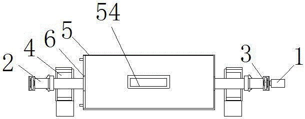
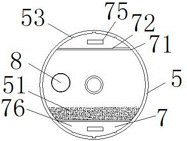
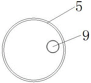
[0018] see Figure 1-6 , the present invention provides a technical solution: a grinding machine for automatically separating waste materials, including a motor 1, the rotor of the motor 1 is movably connected with the rotating shaft 2, and a protective device 3 is provided outside the connection between the rotating shaft 2 and the rotor. 3 It can protect the stability and cleanliness of the connection between the rotating shaft 2 and the rotor, and prevent d...


PUM


Abstract

The invention discloses a grinding machine for automatically separating waste materials, which includes a motor, the rotor of the motor is movably connected with a rotating shaft, and a protection device is arranged on the outside of the connection between the rotating shaft and the rotor, and the outer part of the rotating shaft is connected with the protective device. A supporting device is arranged adjacent to the device, and the outer movable sleeve in the middle of the rotating shaft is equipped with a grinding box, and the joints between the two ends of the grinding box and the rotating shaft are equipped with bearings, and the two inner parts of the grinding box A waste collection device is arranged on the side, and the two ends of the grinding box are respectively fixedly equipped with a material inlet and a material outlet. The grinding machine for automatically separating waste materials utilizes a pullable waste material collector, and the method of setting a screen on the waste material collector can enable the machine to automatically separate waste materials during work, saving time, and the sieve holes of the screen are provided with Slam the door to prevent waste from backflowing and contaminating the abrasive, protect the purity of the abrasive, and achieve the purpose of effectively removing waste.

Description

technical field [0001] The invention relates to the technical field of industrial equipment, in particular to a grinding machine for automatically separating waste materials. Background technique [0002] A grinder is a machine tool that uses abrasive tools to grind the surface of a workpiece. Most grinders use high-speed rotating grinding wheels for grinding, and a few use other abrasive tools such as oil stones, abrasive belts, and free abrasives for processing, such as grinding Machine tools, ultra-finishing machine tools, abrasive belt grinders, grinding machines and polishing machines, grinding machines can process materials with high hardness, such as hardened steel and hard alloy, and can also process brittle materials, such as glass and granite, grinding machines It can be used for grinding with high precision and small surface roughness, and can also perform high-efficiency grinding. However, the existing machines on the market that use free abrasives have polluted ...

Claims


Application Information

Patent Timeline
IPC IPC(8): B24B31/16B24B31/02
CPCB24B31/16B24B31/02
Inventor 高峰
Owner 高峰
Learn More