
Injection molding sprue cutting device

A gate and injection molding technology, which is applied in the field of injection gate removal device, can solve the problems of increased defect rate, uneven removal, low work efficiency, etc., and achieve the effect of reducing the defect rate

Inactive Publication Date: 2016-10-12
INJELIC PRECISION MOLD & PLASTICS
View PDF5 Cites 2 Cited by
  • Summary
  • Abstract
  • Description
  • Claims
  • Application Information

AI Technical Summary

Problems solved by technology

[0002] The existing injection molding gate cutting device has only one cutter head, and when cutting the gate, there are often cases of uneven cutting, resulting in a significant increase in defect rate and low work efficiency

Method used


Image

  • Injection molding sprue cutting device

Examples


Embodiment Construction

[0014] The specific implementation manners of the present invention will be further described below in conjunction with the drawings and examples. The following examples are only used to illustrate the technical solution of the present invention more clearly, but not to limit the protection scope of the present invention.

[0015] The technical scheme of concrete implementation of the present invention is:

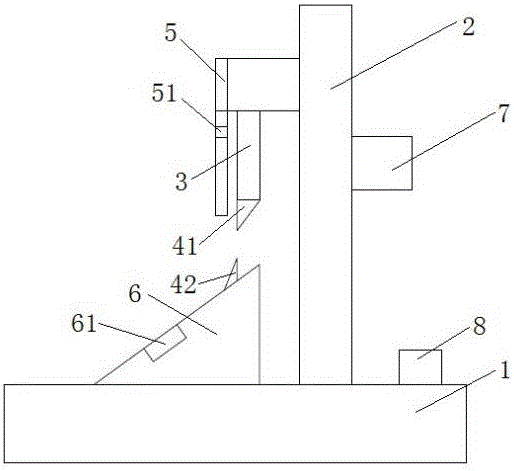
[0016] like figure 1 As shown, an injection molding gate cutting device includes a base 1, which is arranged horizontally, a bracket 2 is provided on the base 1, a cylinder is provided on the bracket 2, and the cylinder includes a piston rod 3, and the piston rod 3 is vertically arranged. Arranged vertically, the bottom end of the above-mentioned piston rod 3 is provided with an upper cutter head 41, and a limiting plate 5 is also installed on the above-mentioned bracket 2. Side, the above-mentioned limit plate 5 is provided with a limit groove 51, the above-mentioned li...


PUM

PropertyMeasurementUnit
Angleaaaaaaaaaa

Abstract

The invention discloses an injection molding sprue cutting device. The device comprises a base; the base is horizontally arranged; a bracket is arranged on the base; a cylinder is arranged on the bracket, and includes a piston rod; the piston rod is vertically arranged; an upper tool bit is arranged at the bottom end of the piston rod; a limiting plate is mounted on the bracket, is vertically mounted, and is positioned on one side of the upper tool bit; a limiting groove is formed in the limiting plate, and is used for limiting the position of an injection part to be cut; a positioning cushion block is mounted on the base, and is provided with a lower tool bit; the position of the lower tool bit is corresponding to the position of the upper tool bit; the cylinder is connected with a controller; the controller is used for controlling the extension speed of the piston rod; and a switch button is mounted on the base, and is connected with the cylinder. The cutting device has the beneficial effects of smooth cutting and prominent reduction of the reject ratio.

Description

technical field [0001] The invention relates to the technical field of injection molding, in particular to an injection molding gate cutting device. Background technique [0002] The existing injection molding gate cutting device has only one cutter head, and when cutting the gate, there is often a situation of uneven cutting, resulting in a significantly increased defect rate and low work efficiency. Contents of the invention [0003] The object of the present invention is to provide an injection molding gate cutting device, the cutting device cuts off smoothly, and the defect rate is significantly reduced. [0004] To achieve the above object, the present invention provides the following technical solutions: [0005] An injection molding gate cutting device, comprising a base, the base is arranged horizontally, a support is provided on the base, a cylinder is provided on the support, the cylinder includes a piston rod, the piston rod is arranged vertically, and the bott...

Claims


Application Information

Patent Timeline
IPC IPC(8): B29C45/38
CPCB29C45/382
Inventor 姜峰
Owner INJELIC PRECISION MOLD & PLASTICS
Learn More