Diaphragm automatic roll changing device

A diaphragm, automatic technology, applied in the direction of winding strips, transportation and packaging, thin material handling, etc., can solve the problems of increasing idle time of equipment, incapable of continuous use of material belts, increasing people and diaphragms, etc., to save time for roll change , Save the time of manual waiting and change the material roll, and improve the work efficiency.

Active Publication Date: 2018-03-20
ZHUHAI HIGRAND ELECTRONICS TECH
View PDF8 Cites 0 Cited by
  • Summary
  • Abstract
  • Description
  • Claims
  • Application Information

AI Technical Summary

Problems solved by technology

[0002] Existing battery manufacturing generally adopts fully automatic winding equipment, but in the production process, the processes of fully automatic winding, lamination, bag making and other processes include the process of unwinding the separator roll material. Currently, single roll material unwinding is generally used. The method of stopping and refueling after the roll is used up, the material tape cannot be used continuously, especially during the winding process of the battery cell, the diaphragm material roll needs to be suspended after use, and the machine is restarted after manual replacement of the new diaphragm material roll. Some diaphragm exchange belt technologies are not completely automatic, which requires human assistance, which reduces the efficiency of the machine, increases the chance of contact between people and the diaphragm, and causes pollution to the diaphragm material; at the same time, it increases the idle time of the equipment and seriously affects the efficiency of the equipment. , resulting in material waste

Method used


Image

  • Diaphragm automatic roll changing device
  • Diaphragm automatic roll changing device
  • Diaphragm automatic roll changing device

Examples


Embodiment Construction

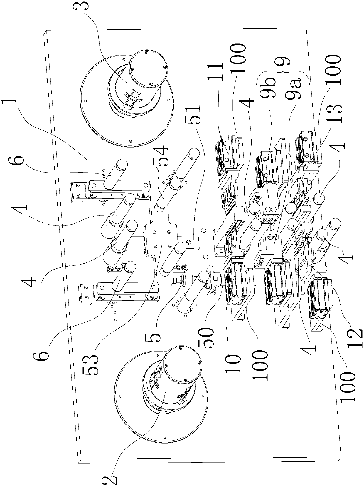
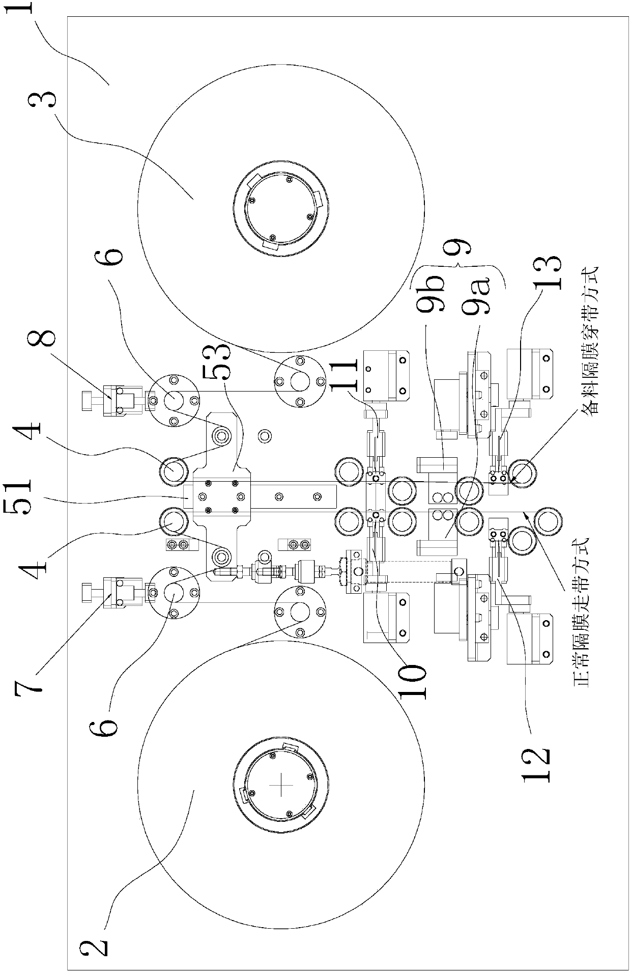
[0031] Diaphragm automatic roll changing device, such as Figure 1 to Figure 8 As shown in the figure, it is used for the winding process of the battery automatic winding machine, including the vertical substrate 1, and the conveying direction of the diaphragm is perpendicular to the substrate 1; the left and right sides of the substrate 1 are respectively equipped with main The material roll mechanism 2 and the spare material roll mechanism 3, the diaphragm material rolls installed on the main material roll mechanism 2 and the spare material roll mechanism 3 are mutually spare for the winding process to provide the released diaphragm in turn; the middle part of the substrate 1 is respectively installed There are two rows of multiple rollers 4 that are convenient for the diaphragms on the main roll mechanism 2 and the spare roll mechanism 3 to carry out material preparation and threading respectively and then tow and freely suspend.

[0032] continue as Figure 1 to Figure 8 ...


PUM


Abstract

The invention relates to an automatic roll changing device for diaphragms. The automatic roll changing device for the diaphragms comprises a vertically-arranged base plate; the conveying direction of the diaphragms is perpendicular to the base plate; a main-use material roll mechanism and a standby material roll mechanism which are standby to each other are arranged on the left side and the right side of the base plate correspondingly; the middle portion of the base plate is provided with a plurality of rolling wheels which make strap penetrating of the diaphragms convenient; a tensioning buffering storage mechanism controlling the tensile force of the diaphragms on the main-use material roll mechanism and the standby material roll mechanism at the same time and providing diaphragm buffering for the winding procedure is installed on the upper portion of the base plate; a diaphragm turning-connection mechanism pasting the head portion of a new diaphragm material roll on the tail portion of the diaphragm which is rolled completely is installed on the lower portion of the base plate; the portion, on the upper side of the diaphragm turning-connection mechanism, of the base plate is provided with an upper left diaphragm excess material cut-off mechanism and an upper right diaphragm excess material cut-off mechanism which are used for cutting off and pressing diaphragm tail portion excess materials of a material roll being about to be used up; and the portion, on the lower side of the diaphragm turning-connection mechanism, of the base plate is provided with a lower left diaphragm traction material cut-off mechanism and a lower right diaphragm traction material cut-off mechanism which are used for cutting off and pressing diaphragm front end traction materials of a traction material roll.

Description

【Technical field】 [0001] The invention relates to winding equipment for battery production, in particular to a diaphragm automatic changing device for electric cores. 【Background technique】 [0002] Existing battery manufacturing generally adopts fully automatic winding equipment, but in the production process, the processes of fully automatic winding, lamination, bag making and other processes include the process of unwinding the separator roll material. Currently, single roll material unwinding is generally used. The method of stopping and refueling after the roll is used up, the material tape cannot be used continuously, especially during the winding process of the battery cell, the diaphragm material roll needs to be suspended after use, and the machine is restarted after manual replacement of the new diaphragm material roll. Some diaphragm exchange belt technologies are not completely automatic, which requires human assistance, which reduces the efficiency of the machin...

Claims


Application Information

Patent Timeline
Patent Type & Authority Patents(China)
IPC IPC(8): B65H19/18B65H19/20B65H23/035
CPCB65H19/18B65H19/20B65H23/035
Inventor 曹海霞陈增杰刘秀娟杨春超乔冠阳
Owner ZHUHAI HIGRAND ELECTRONICS TECH
Why Eureka
Try Eureka