
Flue gas conveyer for two-stage brine purification and method of using same

A brine purification and delivery device technology, applied in the direction of alkali metal halide purification, alkali metal chloride, etc., can solve the problems of equipment impact, affect the normal use of flue gas compressors, reduce service life, etc., achieve stable pressure and simple structure , the effect of low production cost

Active Publication Date: 2016-10-12
雪天盐业集团股份有限公司
View PDF4 Cites 0 Cited by
  • Summary
  • Abstract
  • Description
  • Claims
  • Application Information

AI Technical Summary

Problems solved by technology

[0002] Adding flue gas in the secondary reaction of brine purification is conveyed by the flue gas compressor; , so that the brine in the reaction barrel flows back into the flue gas compressor with the pipeline under the action of siphon, which will have a major impact on the equipment, affect the normal use of the flue gas compressor, and reduce its service life

Method used


Image

  • Flue gas conveyer for two-stage brine purification and method of using same
  • Flue gas conveyer for two-stage brine purification and method of using same

Examples


Embodiment 1

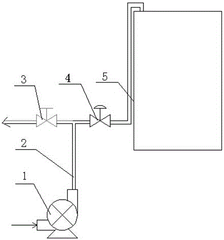
[0018] refer to figure 1 , a flue gas delivery device for secondary brine purification of the present invention, comprising a flue gas compressor 1, a control valve 4 and a safety valve 3; the flue gas compressor 1 is communicated with the flue gas delivery pipe, and the compressed The flue gas is transported to the bottom of the brine purification reaction barrel 5; the flue gas delivery pipe includes a main flue gas delivery pipe 2 and a branch flue gas delivery pipe 6, and the outlet of the branch flue gas delivery pipe 6 and the main flue gas delivery pipe 2 The control valve 4 is provided on the branch smoke delivery pipe 6; one end of the safety valve 3 communicates with the main smoke delivery pipe 2, and the other end communicates with the atmosphere.

[0019] The rated pressure of the safety valve 3 is 0.2MPa.

[0020] The distance between the end of the branch flue gas conveying pipe 2 and the bottom of the brine purification reaction barrel 5 is ≤1.0m.

[0021] In...

Embodiment 2

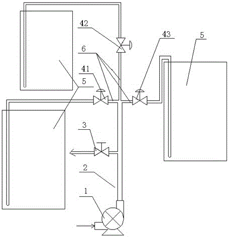
[0025] refer to figure 2 , a flue gas delivery device for secondary brine purification of the present invention, comprising a flue gas compressor 1, 3 control valves 4 and a safety valve 3; the flue gas compressor 1 is communicated with the flue gas delivery pipe, and the compressed The flue gas is transported to the bottom of the brine purification reaction barrel 5; the flue gas delivery pipe includes the main flue gas delivery pipe 2 and 3 branch flue gas delivery pipes 6, and the 3 branch flue gas delivery pipes 6 are connected in parallel to the main flue gas The gas outlet end of the conveying pipe 2; the branch smoke conveying pipe 6 is provided with a control valve 4; one end of the safety valve 3 communicates with the main smoke conveying pipe 2, and the other end communicates with the atmosphere.

[0026] The rated pressure of the safety valve 3 is 0.3MPa.

[0027] The control valve 4 includes a first control valve 41 , a second control valve 42 and a third control...


PUM


Abstract

A flue gas conveyer for two-stage brine purification comprises a flue gas compressor, at least one control valve and a safety valve; the flue gas compressor is communicated with a flue gas conveying pipe, and compressed flue gas is conveyed to the bottom of a brine purification reacting barrel; the flue gas conveying pipe includes a main flue gas conveying pipe and at least one auxiliary flue gas conveying pipe, and each auxiliary flue gas conveying pipe is provided with a control valve; one end of the safety valve is communicated with the main flue gas conveying pipe, and the other end thereof is communicated with air. The invention also discloses a method of using the flue gas conveyer for two-stage brine purification. The flue gas conveyer is simple in structure and low in manufacture cost and is effective in preventing brine in the brine purification reacting barrel from flowing back under siphoning action, thereby prolonging the life of the flue gas compressor.

Description

technical field [0001] The invention relates to a secondary brine purification device, in particular to a flue gas conveying device for secondary brine purification and a use method thereof. Background technique [0002] Adding flue gas in the secondary reaction of brine purification is conveyed by the flue gas compressor; , so that the brine in the reaction barrel flows back into the flue gas compressor with the pipeline under the action of siphon, which has a major impact on the equipment, affects the normal use of the flue gas compressor, and reduces its service life. There is an urgent need to provide a flue gas conveying device for secondary brine purification with stable flue gas conveying pressure, which can avoid siphon phenomenon and prevent pipe bursting. Contents of the invention [0003] The technical problem to be solved by the present invention is: to overcome the deficiencies of the prior art, to provide a flue gas delivery device for secondary brine purifi...

Claims


Application Information

Patent Timeline
Patent Type & Authority Applications(China)
IPC IPC(8): C01D3/04C01D3/14
CPCC01D3/04C01D3/14
Inventor 周中平杨建
Owner 雪天盐业集团股份有限公司
Learn More