A zipper electroplating device

An electroplating device and zipper technology, which are applied to electrolytic components, electrolytic processes, clothing, etc., can solve problems such as affecting the effect of electroplating, zipper dropping grooves, etc., and achieve the effects of convenient socket connection, convenient installation and disassembly, and improved electroplating efficiency.

Active Publication Date: 2018-03-02
CHONGQING PENGLEI AUTO PARTS CO LTD
View PDF6 Cites 0 Cited by
  • Summary
  • Abstract
  • Description
  • Claims
  • Application Information

AI Technical Summary

Problems solved by technology

Although such an electroplating method effectively improves the electroplating efficiency, since the length of the zipper is fixed, during the electroplating process, the first and last ends of the zipper are not easy to wrap around the electroplating guide wheels, so it is easy to appear at the first and last ends of the zipper. Groove drop phenomenon, which affects the effect of electroplating

Method used


Image

  • A zipper electroplating device
  • A zipper electroplating device
  • A zipper electroplating device

Examples


Embodiment 1

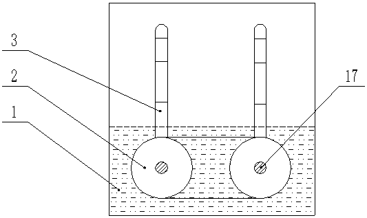
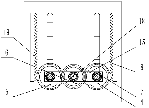
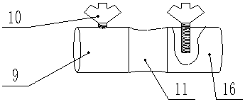
[0020] Example 1, such as figure 1 A kind of zipper electroplating device shown, at first offer two strip holes 3 identical and on the same horizontal plane on the rear wall of the electroplating tank 1, then install a sealing telescopic block 13 in each strip hole 3, and seal the telescopic block 13 structured as Figure 4 As shown, the telescopic sleeves at both ends are slightly larger than the telescopic sleeves in the middle, and the upper and lower ends of the sealed telescopic block 13 are correspondingly fixed on the top and bottom of the strip hole 3, and at the same time, a rolling shaft hole 14 is opened in the middle, and the rolling shaft A rolling shaft 17 is sleeved in the hole 14, and one end of the rolling shaft 17 in the electroplating tank 1 is fixedly provided with a scroll wheel 2, and each scroll wheel 2 outer edge circumference is provided with three roads such as Figure 5 The arc-shaped groove shown.

[0021] Such as figure 2 As shown, the rolling ...

Embodiment 2

[0023] Embodiment 2, the difference with embodiment 1 is: as Image 6 As shown, the web-type roller 20 is used to replace the scroll wheel in Embodiment 1. The web-type roller 20 includes a bush, and the bush is connected to the scroll shaft through a keyway. Four webs are uniformly welded outside the shaft sleeve, and the top of each web is provided with an inwardly concave curved surface. In addition, the web is divided into two parts from the middle, the part near the top is the web shell 21 , and the other part is the web shaft 22 . Such as Figure 7 As shown, the web shell 21 is hollow, the internal cross section is slightly larger than the cross section of the web shaft 22 , and has no bottom surface, and the web shell 21 is sleeved on the top of the web shaft 22 . The top of the web shaft 22 is connected to the inner top of the web shell 21 by a spring 24, and the outer peripheral wall of the bottom of the web shell has a plurality of evenly distributed liquid inlet h...


PUM


Abstract

The invention belongs to the field of electroplating and particularly relates to a zipper electroplating device which comprises an electroplating tank, wherein two strip holes are vertically formed in the side wall of the electroplating tank; a sealing telescopic block is mounted in the strip hole; the upper and lower ends of the sealing telescopic block are fixed at the top and bottom of the strip hole respectively; a rolling shaft hole is formed at the middle part of the sealing telescopic block; a rolling shaft is cooperatively mounted in the rolling shaft hole; a rolling wheel is mounted at the end of the rolling shaft in the electroplating tank; a lifting part and a transmission part are arranged at the end of the rolling shaft outside the electroplating tank; multiple grooves are formed in the outer circumference of the rolling wheel. The zipper electroplating device also comprises connection caps, wherein the connection caps include a left cap and a right cap; fastening nails are arranged on the left cap and the right cap respectively; and a stretching part is arranged between the left cap and the right cap. In the invention, the phenomenon that the head and tail of the zipper easily go off the tank during zipper electroplating is solved; and by reasonably utilizing the transmission characteristic, the transmission efficiency of the device is relatively high, and the power utilization rate is increased.

Description

technical field [0001] The invention relates to the field of electroplating, in particular to a zipper electroplating device. Background technique [0002] Electroplating is the process of plating a layer of other metals or alloys on the surface of parts using the principle of electrolysis. It is a process of using electrolysis to attach a layer of metal film to the surface of metal or other material parts, so as to prevent corrosion and improve wear resistance. , conductivity, reflectivity and aesthetic enhancement. In the zipper electroplating process, it is usually soaked in the electroplating solution for electroplating, but the efficiency of such electroplating is very low, and after the electroplating is completed, it is necessary to manually remove the zipper soaked in the electroplating solution. Personnel have brought great inconvenience, and it is easy to cause damage to people's skin. [0003] The Chinese patent announcement number is CN201058892Y, a zipper elec...

Claims


Application Information

Patent Timeline
Patent Type & Authority Patents(China)
IPC IPC(8): C25D7/02C25D17/00
CPCC25D7/02C25D17/00
Inventor 何令
Owner CHONGQING PENGLEI AUTO PARTS CO LTD
Why Eureka
Try Eureka