
Vibratory leveling device

A technology for leveling devices and vibrating beams, which is applied in laying tracks, roads, tracks, etc., and can solve problems such as poor versatility, inconvenient handling, and cumbersome operations

Active Publication Date: 2016-10-12
中铁十七局集团第三工程有限公司 +2
View PDF7 Cites 7 Cited by
  • Summary
  • Abstract
  • Description
  • Claims
  • Application Information

AI Technical Summary

Problems solved by technology

[0004] At present, during the construction of the base, the existing vibrating equipment has the disadvantages of easy tilting, cumbersome operation and inconvenient transportation due to its poor versatility

Method used


Image

  • Vibratory leveling device
  • Vibratory leveling device
  • Vibratory leveling device

Examples


Embodiment Construction

[0032] The present invention will be further described in detail below in conjunction with the accompanying drawings and specific embodiments.

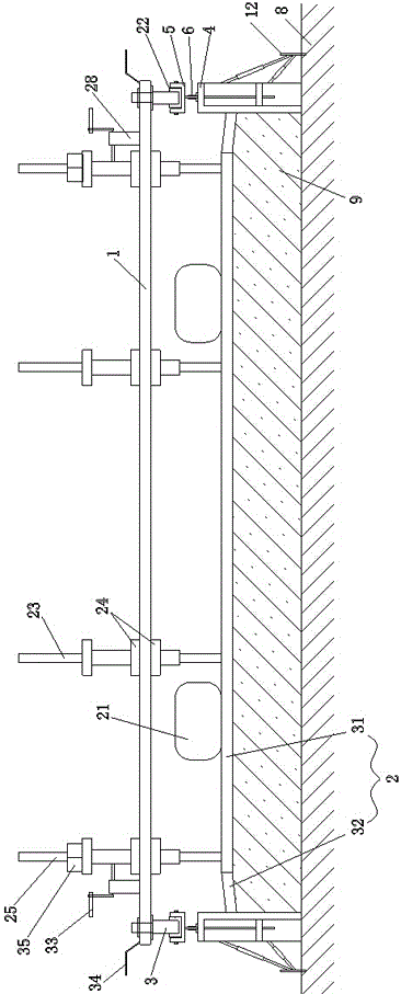
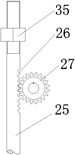
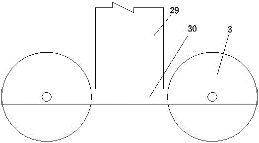
[0033] Such as figure 1 As shown, a vibrating leveling device includes a main beam 1, a vibrating beam 2 and a walking mechanism, the vibrating beam 2 is provided with a vibrator 21, and the main beam 1 is parallel to the vibrating beam 2, It is connected with the vibrating beam 2 through a guiding mechanism. The two ends of the main beam 1 are provided with a height adjustment mechanism for the vibrating beam. , the track groove 22 is connected with the longitudinal template 4 through a support adjustment mechanism.

[0034] The main beam 1 is connected with the vibrating beam 2 through the guiding mechanism, and the vibrating beam 2 is used to vibrate the concrete by using the vibrator 21 on the vibrating beam. The leveling operation of the concrete surface; the height of the vibrating beam 2 is adjusted by means of the height ad...


PUM


Abstract

The invention discloses a vibratory leveling device, and relates to the technical field of concrete construction equipment. The vibratory leveling device comprises a main beam, a vibrating beam and walking mechanisms, wherein vibrators are arranged on the vibrating beam; the main beam is parallel to the vibrating beam, and is further connected with the vibrating beam through a guiding mechanism; vibrating beam height regulating mechanisms are arranged at two ends of the main beam; the walking mechanisms are arranged at two ends of the maim beam; roller wheels at the lower ends of the walking mechanisms cooperate with an orbital groove; the orbital groove is connected with a longitudinal template through a supporting regulating mechanism. A vibratory leveling operation is carried out by utilizing the vibrators on the vibrating beam; the vibrating beam height regulating mechanisms at the two ends of the main beam can regulate the height of the vibrating beam, thereby being convenient for crossing an obstacle; the roller wheels at the lower ends of the walking mechanisms at the two ends cooperate with the orbital groove; the orbital groove can be connected with the longitudinal template through the supporting regulating mechanism; heights and levelness degrees of the orbital groove and a vibrating device are regulated by means of the supporting regulating mechanism; the orbital groove and the supporting regulating mechanism are convenient to disassemble without influencing the recycling of the longitudinal template; the universality is improved; the material consumption is reduced.

Description

technical field [0001] The invention relates to the technical field of concrete construction equipment, in particular to a vibrating leveling device. Background technique [0002] CRTSⅢ ballastless track is a new type of unit slab ballastless track structure independently developed by my country. It consists of rails and fasteners, prefabricated track slabs, self-compacting concrete structure filling layers, isolation layers, and steel bars with limiting grooves from top to bottom. Concrete base composition, such as Figure 13 shown. [0003] Among them, the base is the transitional structural layer between the CRTSⅢ slab ballastless track bed structure and the offline engineering infrastructure (subgrade, tunnel, bridge, etc.), and it is the cast-in-place reinforced concrete base of the ballastless track. The width of the base is greater than the width of the track slab, and drainage slopes are provided within 30cm of the sides of the base to prevent rainwater from flowing ...

Claims


Application Information

Patent Timeline
Patent Type & Authority Applications(China)
IPC IPC(8): E01B29/00
CPCE01B29/00
Inventor 曹会芹王新民唐波涛周永明贺雷宁李浩宇
Owner 中铁十七局集团第三工程有限公司
Learn More