Straddle-type movable-butting track beam and use method thereof

A track beam and straddle technology, applied in tracks, roads, buildings, etc., can solve problems such as affecting the landscape of vehicle bases and increasing engineering investment, and achieve the effect of facilitating crossing of roads, saving engineering investment and ensuring safety.

Pending Publication Date: 2017-09-19
CHINA RAILWAY ENG CONSULTING GRP CO LTD
View PDF7 Cites 2 Cited by
  • Summary
  • Abstract
  • Description
  • Claims
  • Application Information

AI Technical Summary

Problems solved by technology

[0003] In the existing monorail traffic system, the laying of the vehicle base is mainly based on the ground line. When the track beam crosses the road, it is necessary to use the elevated line and the underground line. However, the use of the underground line will greatly increase the project investment, and the elevated line will increase the investment. while also affecting the landscape of the vehicle base

Method used


Image

  • Straddle-type movable-butting track beam and use method thereof
  • Straddle-type movable-butting track beam and use method thereof
  • Straddle-type movable-butting track beam and use method thereof

Examples


Embodiment 1

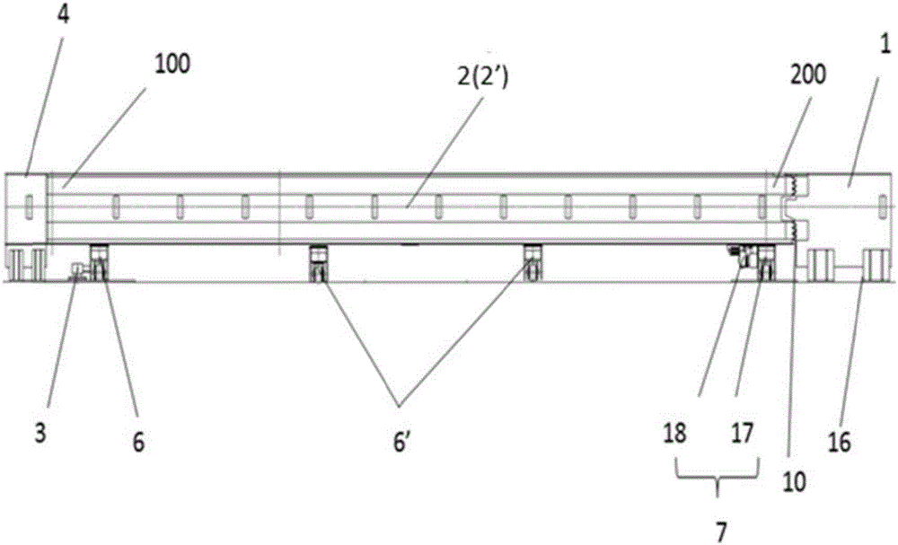
[0037] like Figure 1-3 As shown, the straddle-type movable docking track beam of the present invention includes a first track beam 2, a second track beam 2', a driving device 7 and a rotating device 3, and the first track beam 2 and the second track beam 2 ' have the same structure, both have a pivot end 100 and a movable end 200, and the first track beam 2 and the second track beam 2' are respectively arranged on both sides of the road;

[0038] The two groups of driving devices 7 are respectively connected to each of the movable ends 200 (or positions close to the movable ends 200, as long as it is convenient to push the movable ends 200 to swing), and are used to drive the track beams 2 and 2' Swing with the pivot end 100 as the center of rotation;

[0039] The two groups of rotating devices 3 are connected to the pivot ends 100 respectively, and are used to rotate under the drive of the driving device 7;

[0040] The movable ends 200 of the first track beam 2 and the se...

Embodiment 2

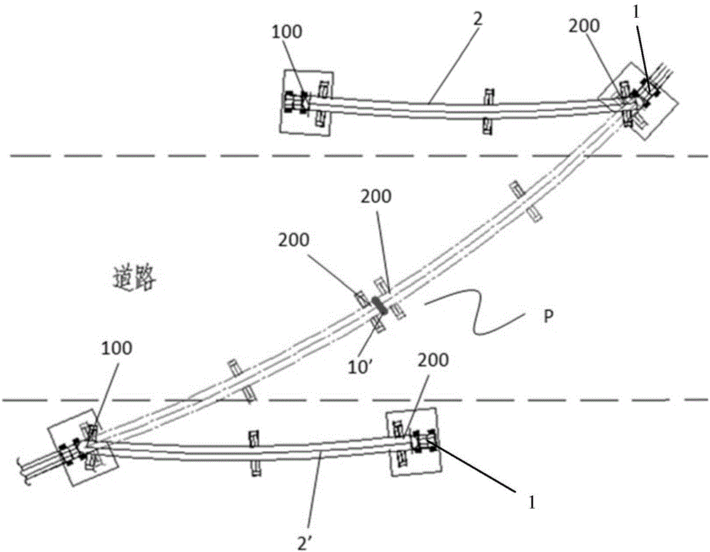
[0053] like Figure 5 As shown, the present invention also provides a method for using the above-mentioned straddle-type movable track beam that can cross the road, which includes the following steps:

[0054] S1, release the locking of the first locking device 10 of the movable end 200 of the first track beam 2 and the second track beam 2' according to the instruction;

[0055] S2. The driving device 7 releases the power to drive the movable ends 200 of the first track beam 2 and the second track beam 2' to swing with the respective pivot ends 100 as the center of rotation;

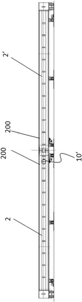
[0056] S3. The movable ends 200 of the first track beam 2 and the second track beam 2' drive the respective pivot ends 100 to rotate, so that the movable ends 200 of the first track beam 2 and the second track beam 2' Docking is carried out under the drive of the driving device 7 to form a running line P across the road;

[0057] S4. After the movable ends 200 of the first track beam 2 and the second t...


PUM


Abstract

The invention discloses a straddle-type movable-butting track beam. The straddle-type movable-butting track beam comprises a first track beam, a second track beam, a driving device and a rotating device, wherein the first track beam and the second track beam are respectively arranged on two sides of a road; the driving device is separately used for driving the first track beam and the second track beam to swing by using the separate pivot ends as rotation centers; and the movable ends, which are respectively arranged on two sides of the road, of the first track beam and the second track beam are butted under the driving of the driving device to form an operating line across the road. According to the straddle-type movable-butting track beam disclosed by the invention, when no train passes, the two track beams are respectively located on one side of the road without influencing traffic; and when a train passes, the entire track beams can switch the train to another track under the action of the driving device, so that the two track beams are butted and the traffic lines on two sides of the road are connected.

Description

technical field [0001] The invention relates to the technical field of monorail traffic, in particular to a straddle-type movable butt joint track beam and a use method thereof. Background technique [0002] Straddle-type monorail traffic is a traffic system in which a track beam is used as a rail, and the train runs on the track beam as a straddle, that is, a single track beam is used to support, stabilize and guide the movement of the train. The technical characteristics are mainly reflected in the three aspects of the vehicle bogie, track beam and line switch. The running mechanism is completely different from the steel wheel and rail system, and the track beam bears a large torsional load. It can be seen from the above records that straddle-type monorail railway has the characteristics of less space, good terrain adaptation, comfort and environmental protection; it is more suitable for use in cities with complex terrain. [0003] In the existing monorail traffic system,...

Claims


Application Information

Patent Timeline
Patent Type & Authority Applications(China)
IPC IPC(8): E01B25/24
CPCE01B25/24
Inventor 林耀雷慧锋刘亚东李雅红张建东于胜利解丽霞
Owner CHINA RAILWAY ENG CONSULTING GRP CO LTD
Why Eureka
Try Eureka