Automatic inspection robot for inspecting power transmission line of photovoltaic power station
A transmission line, automatic inspection technology, applied in photovoltaic power generation, photovoltaic module support structure, photovoltaic modules and other directions, can solve the problems of insufficient inspection work, inspection devices crossing the warning ball, poor battery life, etc., to improve the use of Fault Tolerance and Practical, Convenience, and Efficiency
- Summary
- Abstract
- Description
- Claims
- Application Information
AI Technical Summary
Problems solved by technology
Method used
Image
Examples
Embodiment 1
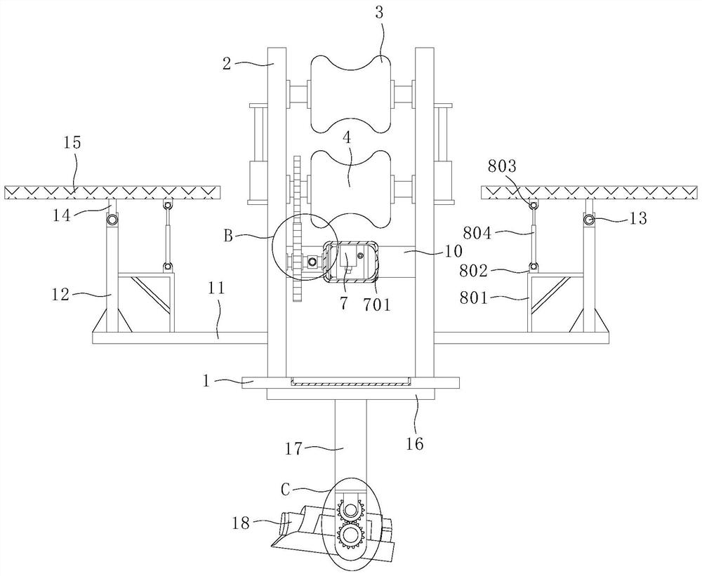
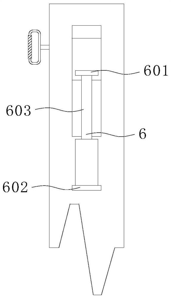
[0027] see Figure 1-6 , the present invention provides a technical solution: an automatic inspection robot for inspection of power transmission lines in photovoltaic power plants, including a support plate 1, two sets of lining plates 2 are fixedly installed on the top of the support plate 1, and the relative positions of the two sets of lining plates 2 The adjacent side walls are provided with buffer wheels 3, and the adjacent side walls of the two sets of lining plates 2 are rotatably installed with walking wheels 4, and the lining plates 2 are provided with an assembly mechanism 5 and a distance adjustment mechanism 6, and the adjacent side walls of the two sets of lining plates 2 The base plate 10 is fixedly installed, the front side of the base plate 10 is provided with a traveling mechanism 7, and the outer wall of one side of the two sets of lining plates 2 is provided with a solar panel 15, and the bottom of the solar panel 15 is provided with an inclination adjustment...
Embodiment 2
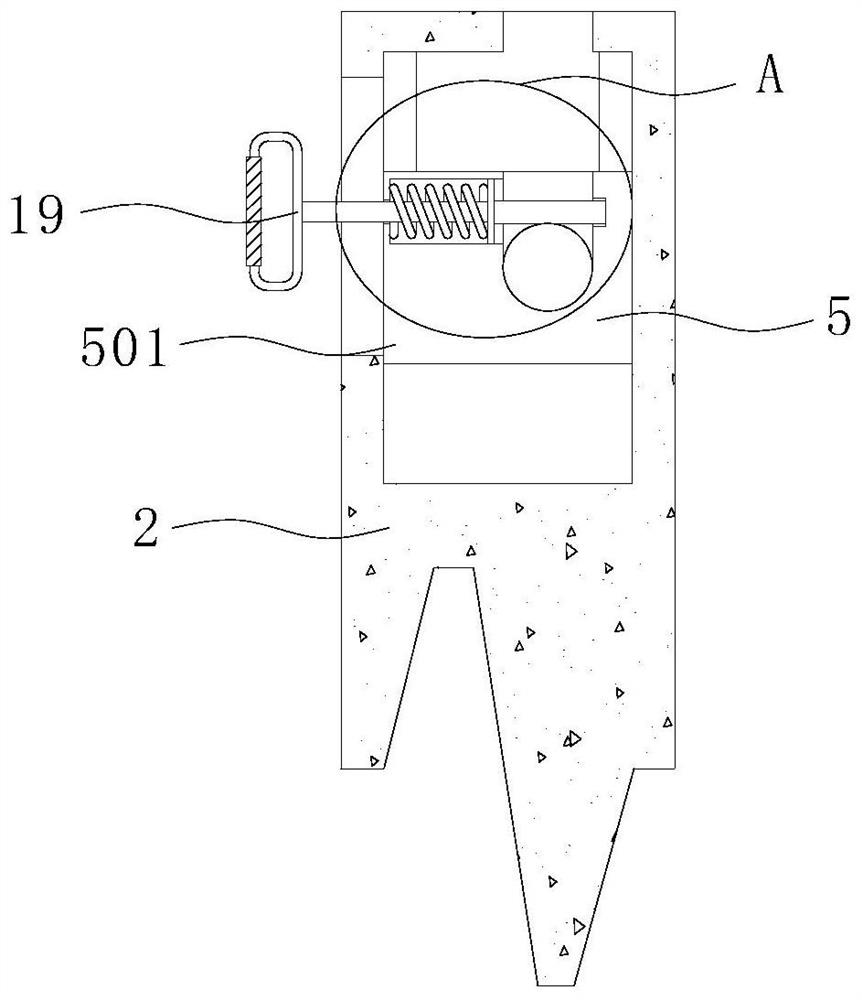
[0031] see Figure 1-6, on the basis of Embodiment 1, the assembly mechanism 5 includes a slider 501, a spring 502, a vertical plate 503, a clamping column 504, a round rod 505 and a pull rod 506, and a chute is provided on the liner 2, and the chute is slidably installed There is a slider 501, and the top of the slider 501 is provided with an annular slot, and both ends of the buffer wheel 3 are rotatably connected with a round rod 505, and the round rod 505 is located in the annular slot, and the slider 501 is provided with a positioning groove, and the positioning slot A spring 502 is fixedly installed on the inner wall of the rear side of the rear side, and a vertical plate 503 is fixedly installed on one end of the spring 502, and a clamp post 504 is fixedly installed on the front side of the vertical plate 503, and a positioning hole is provided in the annular slot, and one end of the clamp post 504 extends to In the positioning hole, a pull rod 506 is fixedly installed ...
PUM
 Abstract
Description
Claims
Application Information
 - R&D
- Intellectual Property
- Life Sciences
- Materials
- Tech Scout
- Unparalleled Data Quality
- Higher Quality Content
- 60% Fewer Hallucinations
Browse by: Latest US Patents, China's latest patents, Technical Efficacy Thesaurus, Application Domain, Technology Topic, Popular Technical Reports.
© 2025 PatSnap. All rights reserved.Legal|Privacy policy|Modern Slavery Act Transparency Statement|Sitemap|About US| Contact US: help@patsnap.com


