
Speed ​​bump based on rfid wireless communication

A technology of wireless communication and speed bumps, which is applied in traffic signals, roads, buildings, etc., can solve problems such as noise pollution, hidden safety hazards, and misunderstandings, and achieve the effects of flexible speed limit control, ingenious design, and simple structure

Active Publication Date: 2019-07-12
WUHAN UNIV OF TECH
View PDF7 Cites 0 Cited by
  • Summary
  • Abstract
  • Description
  • Claims
  • Application Information

AI Technical Summary

Problems solved by technology

The noise marking mainly relies on the noise generated by the passing motor vehicles to remind the driver to slow down. Although the deceleration effect is obvious, it has a certain impact on the driver's physical and mental health, and it is easy to cause noise pollution; the three-dimensional speed bump adopts three-dimensional pre-formed reflective The road markings made of markings remind the driver to slow down through visual illusions, which will be ignored by experienced drivers, and there are still potential safety hazards; visual folding speed bumps are small rubber objects standing on the road, using the driver's Visual impact, but often mistaken for a roadblock, there are deficiencies in use
[0005] Therefore, although people have made a lot of improvements to the traditional deceleration belts, they still cannot solve the driving comfort and speed limit at the same time.

Method used


Image

  • Speed ​​bump based on rfid wireless communication
  • Speed ​​bump based on rfid wireless communication
  • Speed ​​bump based on rfid wireless communication

Examples

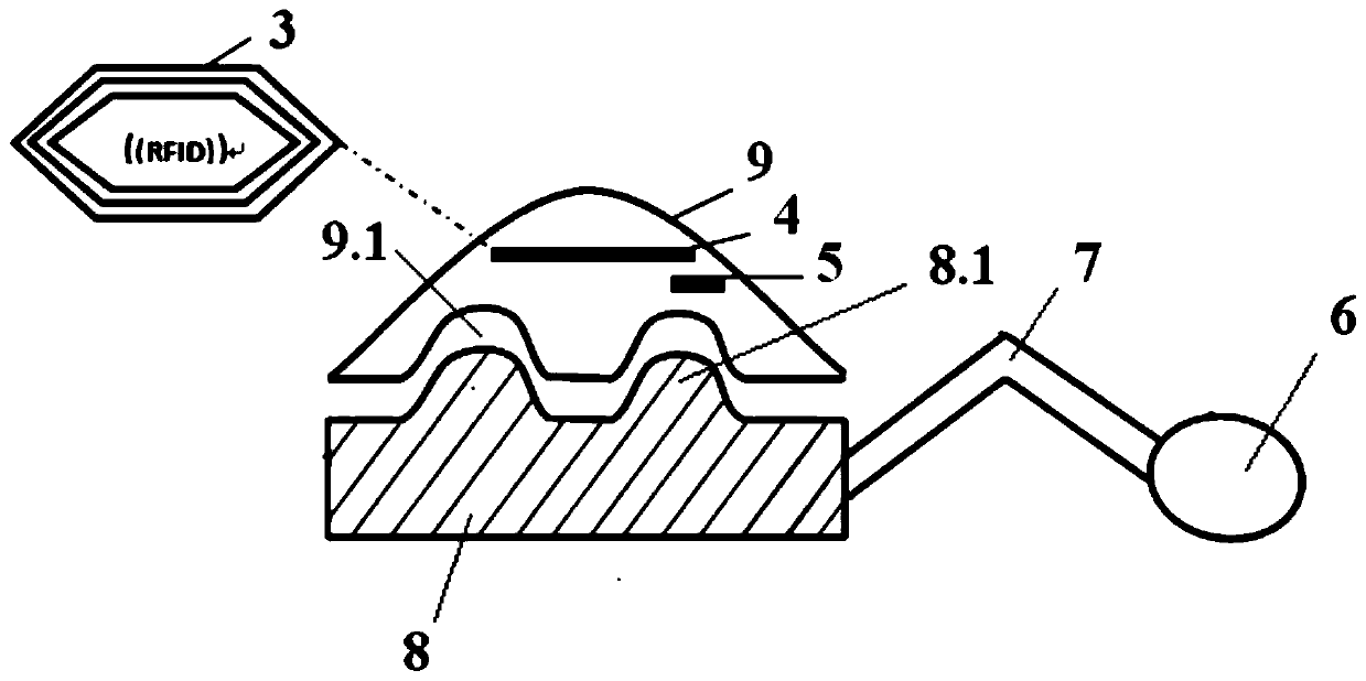
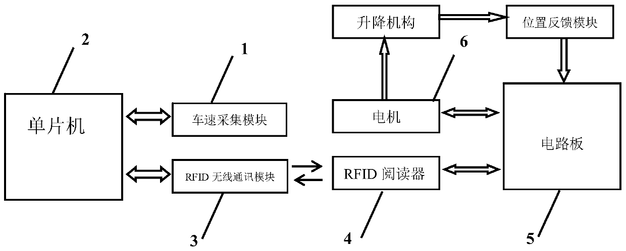
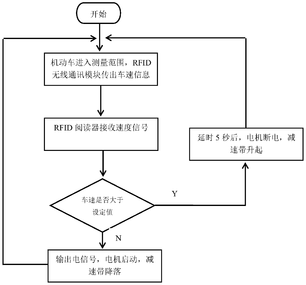

Embodiment Construction

[0026] In order to have a clearer understanding of the technical features, purposes and effects of the present invention, the specific implementation manners of the present invention will now be described in detail with reference to the accompanying drawings.

[0027] Such as Figure 1-3 As shown, the present invention is based on the speed bump of RFID wireless communication, including:

[0028] The vehicle speed acquisition module 1 is arranged on the motor vehicle and is used for collecting vehicle speed signals;

[0029] The single-chip microcomputer 2 is used to convert the vehicle speed signal into the real-time vehicle speed of the motor vehicle by pulse counting;

[0030] The RFID wireless communication module 3 is used for transmitting the real-time vehicle speed wirelessly;

[0031] RFID reader 4 is used for wirelessly receiving real-time vehicle speed information and outputting it to circuit board 5;

[0032] The circuit board 5 is used to compare the real-time v...


PUM


Abstract

The invention discloses a deceleration strip based on RFID (radio frequency identification device) wireless communication. The deceleration strip comprises a vehicle speed acquisition module, a singlechip, an RFID wireless communication module, an RFID reader, a circuit board and a lifting mechanism, wherein the vehicle speed acquisition module is arranged on a motor vehicle and used for acquiring vehicle speed signals; the singlechip is used for converting the vehicle speed signals into real-time vehicle speed through pulse counting; the RFID wireless communication module is used for wirelessly sending out the real-time vehicle speed; the RFID reader is used for wirelessly receiving the real-time vehicle speed information and outputting to the circuit board; the circuit board is used for comparing the real-time vehicle speed with a limited speed value and outputting electric signals; and the lifting mechanism comprises a motor, a foldable rod, a mobile station and a lifting deceleration strip, and the motor and the circuit board are connected through a wire to receive the electric signals. The deceleration strip disclosed by the invention has the advantages that the lifting deceleration strip descends to guarantee smooth running of the motor vehicle when the motor vehicle travels at a speed as required in a speed limiting road section; and the lifting deceleration strip keeps in a lifted state when the motor vehicle does not travel at the speed as required in the speed limiting road section, and the motor vehicle can jolt when passing through the speed limiting road section, so as to remind a driver to decelerate.

Description

technical field [0001] The invention relates to the field of wireless communication, more specifically, to a speed bump based on RFID wireless communication. Background technique [0002] RFID, also known as radio frequency identification technology, is a wireless communication technology that identifies specific targets and reads and writes data through radio signals. Its advantages enable non-contact identification, can work in dust, snow, fog, ice and other environments, and can penetrate non-metallic and non-transparent materials such as wood and plastic when covered, and has strong penetrability, enabling barrier-free reading. In addition, RFID tags can repeatedly add, modify, and delete the information stored in RFID, which is more flexible in practice and requires high compatibility with the speed of different road sections. [0003] The traditional speed bump can effectively limit the speed of the vehicle, but because of the severe vibration and the friction of some...

Claims


Application Information

Patent Timeline
Patent Type & Authority Patents(China)
IPC IPC(8): E01F9/529G08C17/02
CPCG08C17/02
Inventor 徐小强黎苗苗
Owner WUHAN UNIV OF TECH
Learn More