
Vortex-eliminating structure for suction sump of pump station

A technology for water inlet pools and pump stations, which is applied in pump stations, water conservancy projects, water supply devices, etc. It can solve problems such as the difficulty of completely eliminating the vortex of the trumpet tube, the reduction of the water inlet section, and the insufficient suction flow of the water pump, etc., so as to improve the operating efficiency and The effects of running stability, eliminating vortex belt, and simple structure

Active Publication Date: 2016-10-12
CHINA AGRI UNIV
View PDF8 Cites 8 Cited by
  • Summary
  • Abstract
  • Description
  • Claims
  • Application Information

AI Technical Summary

Problems solved by technology

Because the diversion cone occupies a certain space under the trumpet tube, the water inlet section becomes smaller, there is a risk of insufficient suction flow of the water pump, and it will also cause vortex generation in other positions while eliminating the original vortex; and the strip vortex elimination plate Often only the vortex in a certain direction can be eliminated, and it is difficult to completely eliminate the vortex near the horn tube

Method used


Image

  • Vortex-eliminating structure for suction sump of pump station
  • Vortex-eliminating structure for suction sump of pump station
  • Vortex-eliminating structure for suction sump of pump station

Examples


Embodiment Construction

[0036] Embodiments of the present invention will be further described in detail below in conjunction with the accompanying drawings and examples. The following examples are used to illustrate the present invention, but should not be used to limit the scope of the present invention.

[0037] In the description of the present invention, unless otherwise specified, "plurality" means two or more; unless otherwise specified, the top and bottom surfaces of the trumpet tube are circular. The orientation or positional relationship indicated by the terms "upper", "lower", "front end", "rear end", "head", "tail", etc. is based on the orientation or positional relationship shown in the drawings, and is only for convenience of description The present invention and simplified description do not indicate or imply that the device or element referred to must have a specific orientation, be constructed and operate in a specific orientation, and thus should not be construed as limiting the pres...


PUM


Abstract

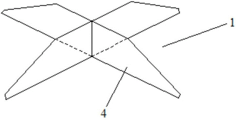
The invention relates to the field of pump station engineering, and in particular relates to a vortex-eliminating structure for a suction sump of a pump station. The vortex-eliminating structure for the suction sump of the pump station comprises a vortex-eliminating plate and a horn-shaped pipe, wherein a water pump water inlet pipe is connected to the top end of the horn-shaped pipe, a water inlet is formed in the bottom end of the horn-shaped pipe, the vortex-eliminating plate is horizontally arranged below the bottom end of the horn-shaped pipe, the cross section of the vortex-eliminating plate is X-shaped, and the vortex-eliminating plate is used for eliminating vortexes near the horn-shaped pipe. With the vortex-eliminating structure for the suction sump of the pump station, the vortex strips near the horn-shaped pipe can be effectively eliminated, so that the uniformity of the water flow entering a pump can be improved, and further, the operating efficiency and stability of the water pump can be improved.

Description

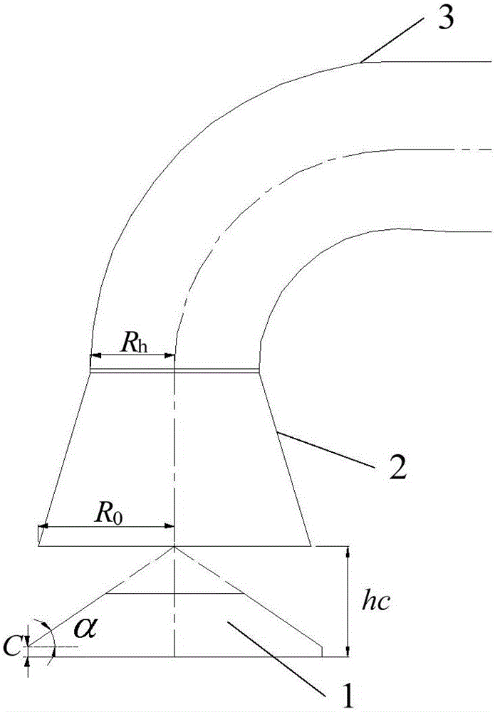
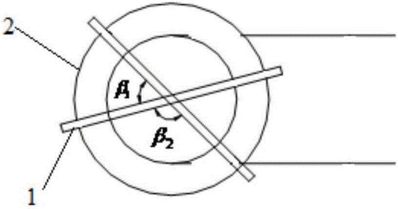
technical field [0001] The invention relates to the field of pumping station engineering, in particular to a vortex-eliminating structure of a pumping station inlet pool. Background technique [0002] The trumpet tube of the water inlet tank of the pump station is directly connected to the water inlet pipe of the water pump, which has a great influence on the flow state of the water pump inlet. There are often suction vortex, bottom vortex and side wall vortex near the trumpet tube. These are important factors affecting the water flow pattern of the pump, and also important factors affecting the efficiency and stable operation of the pump. In order to improve the flow state near the horn tube, scholars at home and abroad have added a diversion cone (conical frustum) or a strip-shaped vortex-eliminating plate under the horn tube. Because the diversion cone occupies a certain space under the trumpet tube, the water inlet section becomes smaller, there is a risk of insufficien...

Claims


Application Information

Patent Timeline
Patent Type & Authority Applications(China)
IPC IPC(8): E03B5/02E02B8/06
CPCE02B8/06E03B5/025
Inventor 王福军资丹姚志峰肖若富叶长亮
Owner CHINA AGRI UNIV
Learn More