Large-span roof steel truss structure and accumulative slipping construction technology
A cumulative slip, long-span technology, applied in truss-type structures, girders, trusses, etc., can solve problems such as affecting the working efficiency of guide rails, complicated installation engineering, and constraints on the development of large-span trusses.
- Summary
- Abstract
- Description
- Claims
- Application Information
AI Technical Summary
Problems solved by technology
Method used
Image

Examples
Embodiment
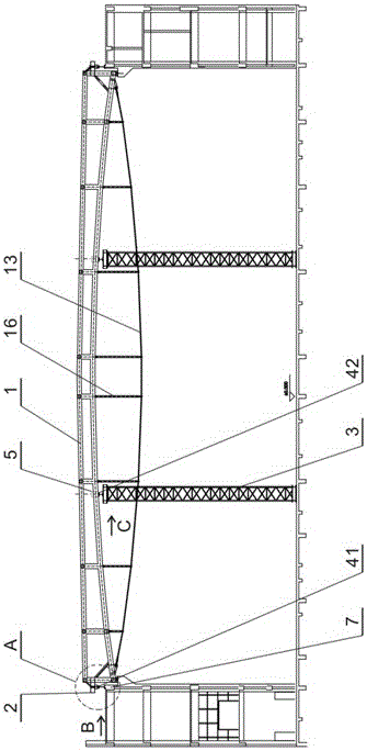
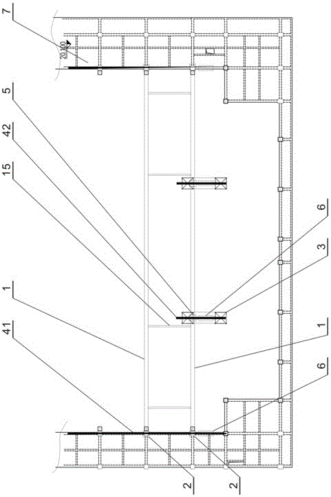
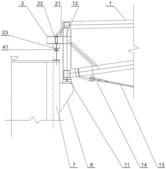
[0044] refer to figure 1 , figure 2 , image 3 , the present invention takes the manufacture and installation of an arched truss in a sports center as an example. The arched truss 1 is a multi-segment long-span truss structure. The arched truss 1 has a total of 10 trusses, and each single truss is connected by three trusses. Formed, the two ends of the arched truss 1 are provided with mounting seats 11, sliding shoe seats 12 and steel rope rigging 14, between the two steel ropes 14 of the arched truss 1 are provided with steel cables 13 along the lower chord, and the arched truss 1 and steel cables 13 are provided with several support rods 16.
[0045] refer to figure 1 , figure 2 , image 3 , the installation method of the truss of the present invention is as follows, the installation of the arch truss 1 of this stadium is carried out after the civil works are completed, that is, the two rows of structural columns 8 of the civil works and the parapets 7 arranged symmet...
PUM
 Abstract
Description
Claims
Application Information