centrifugal compressor

A centrifugal compressor and oil separator technology, applied in the field of compressors, can solve the problems of uneven distribution of oil-mist-gas mixed flow field, low oil-mist separation efficiency, and large built-in space, so as to ensure the oil-mist separation effect, Improve the effect of oil mist separation and flow uniformity

Active Publication Date: 2018-09-07
CHONGQING MIDEA GENERAL REFRIGERATING EQUIP
View PDF7 Cites 0 Cited by
  • Summary
  • Abstract
  • Description
  • Claims
  • Application Information

AI Technical Summary

Problems solved by technology

The oil mist separation efficiency of the external oil mist separation system is low, and the built-in oil mist separation system has an asymmetrical structural design, a large space required for the built-in, more invalid space, uneven distribution of the oil mist gas mixing flow field, and low oil mist separation efficiency

Method used


Image

  • centrifugal compressor
  • centrifugal compressor
  • centrifugal compressor

Examples


Embodiment Construction

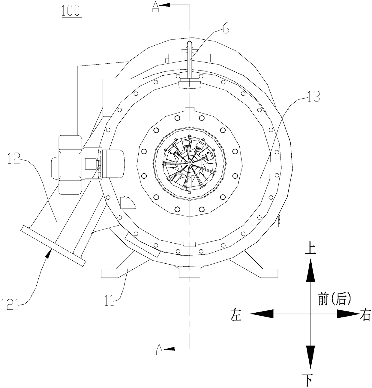
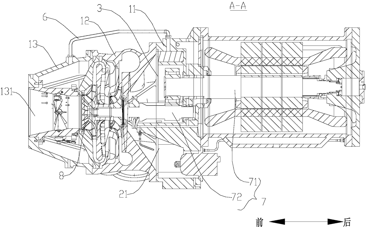
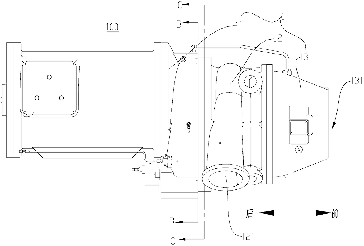
[0027] Embodiments of the invention are described in detail below, examples of which are illustrated in the accompanying drawings. The embodiments described below by referring to the figures are exemplary and are intended to explain the present invention and should not be construed as limiting the present invention.

[0028] In describing the present invention, it is to be understood that the terms "center", "upper", "lower", "front", "rear", "left", "right", "vertical", "horizontal", The orientation or positional relationship indicated by "top", "bottom", "inner", "outer", "axial", "radial", and "circumferential" are based on the orientation or positional relationship shown in the drawings, and are only In order to facilitate the description of the present invention and simplify the description, it does not indicate or imply that the device or element referred to must have a specific orientation, be constructed and operated in a specific orientation, and thus should not be co...


PUM


Abstract

The invention discloses a centrifugal compressor. The centrifugal compressor comprises an outer shell, partition plates, two primary oil separators and a secondary oil separator, wherein the outer shell comprises a supporting shell body, a volute and an inlet shell body, the volute is arranged in front of the supporting shell body, and a containing cavity is defined between the volute and the supporting shell body; an air inlet is formed in the air inlet shell body; the containing cavity is divided into a built-in oil tank and two coolant cavities through the partition plates; the two primary oil separators are arranged corresponding to the two coolant cavities in a one-to-one mode, each primary oil separator comprises a primary inlet, a primary oil outlet and a primary coolant outlet, each primary inlet and each primary oil outlet communicate with the built-in oil tank, and each primary coolant outlet communicates with the corresponding coolant cavity; and the secondary oil separator comprises a secondary inlet, a secondary oil outlet and a secondary coolant outlet, the secondary inlet communicates with both the coolant cavities, the secondary oil outlet communicates with the built-in oil tank, and the secondary coolant outlet communicates with the air inlet. According to the centrifugal compressor, the oil mist separation effect is improved.

Description

technical field [0001] The invention relates to the technical field of compressors, in particular to a centrifugal compressor. Background technique [0002] In a centrifugal compressor, some refrigerant is inevitably mixed in the lubricating oil, especially in a refrigeration system with a high evaporation pressure, the amount of refrigerant mixed in the lubricating oil is more. The refrigerant mixed in the lubricating oil will not only affect the effective lubrication of the lubricating oil to the bearing system of the centrifugal compressor and other moving parts, but also affect the reliability of the centrifugal compressor and the refrigeration system. [0003] The existing oil mist separation systems of centrifugal compressors are roughly divided into external oil mist separation systems and built-in oil mist separation systems. The oil mist separation efficiency of the external oil mist separation system is low, and the built-in oil mist separation system has an asymm...

Claims


Application Information

Patent Timeline
Patent Type & Authority Patents(China)
IPC IPC(8): F04D17/10F04D29/00F04D29/063
CPCF04D17/10F04D29/002F04D29/063
Inventor 张海洲
Owner CHONGQING MIDEA GENERAL REFRIGERATING EQUIP
Why Eureka
Try Eureka