High-efficiency solar indoor heating system

A heating system and solar energy technology, applied in the field of solar energy, can solve the problems such as the large area of ​​the heat collecting unit, and achieve the effects of high heating rate, effective utilization, and low power consumption

Active Publication Date: 2016-10-12
WUHU BEST NEW ENERGY DEV
View PDF7 Cites 0 Cited by
  • Summary
  • Abstract
  • Description
  • Claims
  • Application Information

AI Technical Summary

Problems solved by technology

In modern times, it is generally used to generate electricity or provide energy for water heaters. In the field of water heaters, although the current solar water supply systems have high efficiency, most of them are single structures, and the heat collection units occupy a large area.

Method used


Image

  • High-efficiency solar indoor heating system
  • High-efficiency solar indoor heating system
  • High-efficiency solar indoor heating system

Examples


Embodiment Construction

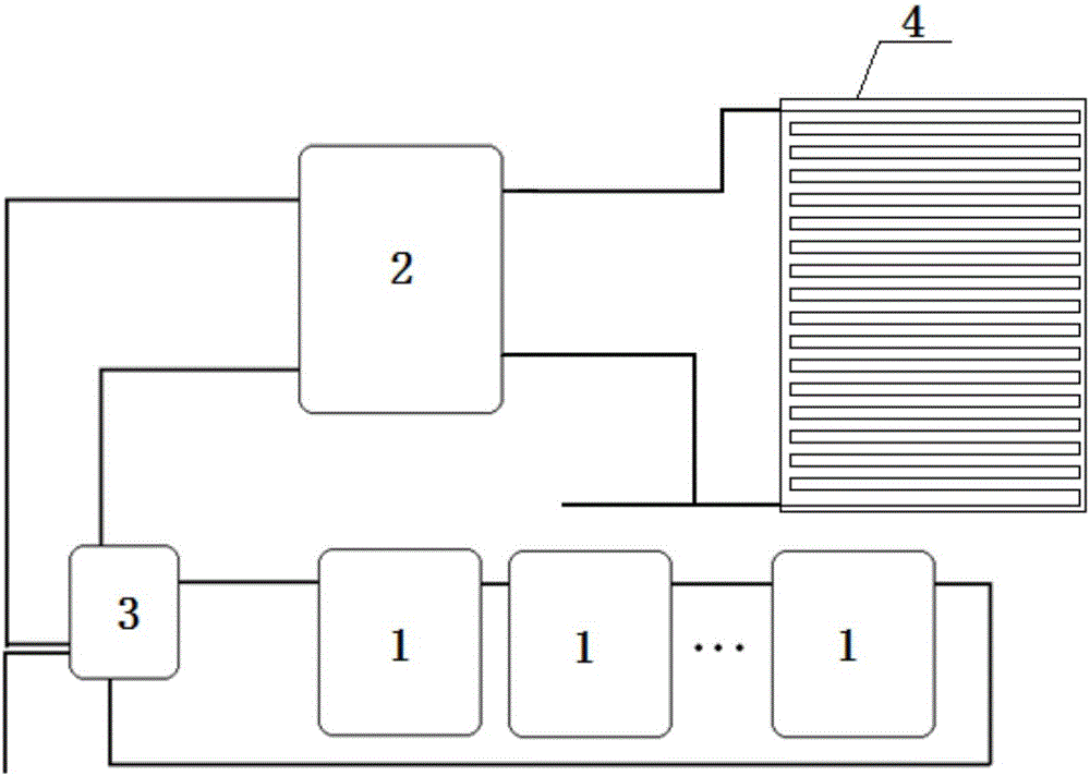
[0043] High-efficiency solar indoor heating system, including heat collection unit 1, layered water storage tank 2, indoor heating unit 4 and intermediate water tank 3, each unit is described in detail below:

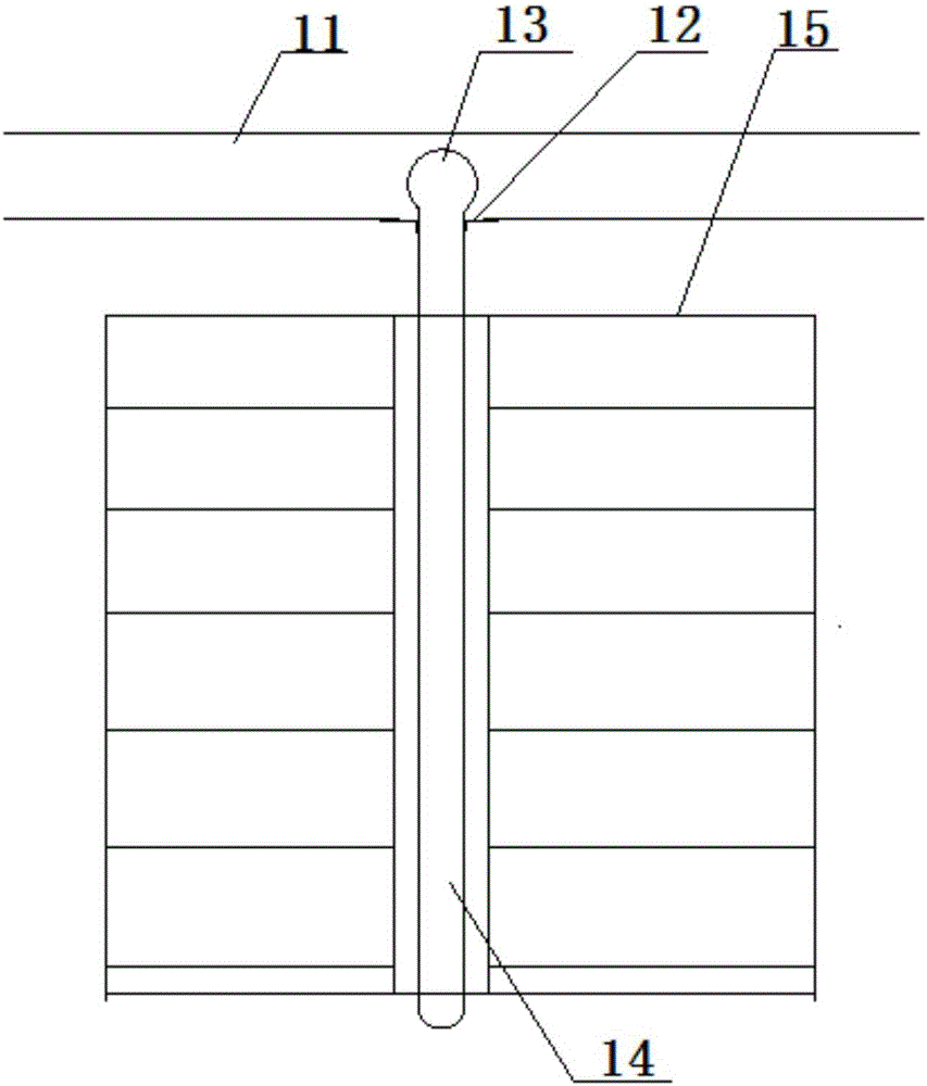
[0044] The heat collecting unit 1 includes a sub-heat collecting pipe 11, a leak-proof pipe pad 12, a heat exchange head 13, a vacuum pipe 14, and a heat collecting plate 15. The vacuum pipe 14 is a hollow straight pipe with both ends sealed. Medium, the vacuum tube 14 is welded on the heat collecting plate 15, and fully contacted, so that the solar heat absorbed by the heat collecting plate 15 will be transferred to the vacuum tube 14, and the medium in the vacuum tube 14 will heat up and generate heat convection at the same time, and transfer the high temperature medium to the vacuum tube 14 top.

[0045] The top of the vacuum tube 14 is a heat exchange head 13, which communicates with the vacuum tube 14, and the heat exchange head 13 is placed in the sub-heat collect...


PUM


Abstract

The invention discloses a high-efficiency solar indoor heating system. The high-efficiency solar indoor heating system comprises a heat collecting unit, a layered water storage tank, an indoor heating unit and a middle water tank. The high-efficiency solar indoor heating system has the advantages of low occupied power, high heating rate and capability of effectively using hot water.

Description

technical field [0001] The present invention relates to the field of solar energy. Background technique [0002] Solar energy refers to the thermal radiation energy of the sun, the main performance is often said that the sun's rays. In modern times, it is generally used to generate electricity or provide energy for water heaters. In the field of water heaters, although the current solar water supply systems have high efficiency, most of them are single structures, and the heat collection units occupy a large area. Contents of the invention [0003] The technical problem to be solved by the present invention is to realize a solar energy system with a small space occupied by the heat collecting unit and high heating efficiency. [0004] In order to achieve the above object, the technical solution adopted by the present invention is: a high-efficiency solar energy indoor heating system, including a heat collecting unit, an indoor heating unit, a layered water storage tank an...

Claims


Application Information

Patent Timeline
Patent Type & Authority Applications(China)
IPC IPC(8): F24D11/00F24D19/10F24J2/22F24J2/24E04B2/88F24S10/55F24S10/70
CPCY02B10/20Y02B10/70Y02E10/44F24D11/003E04B2/88F24D19/1009F24D2200/14F24S10/55F24S10/70
Inventor 方凯
Owner WUHU BEST NEW ENERGY DEV
Why Eureka
Try Eureka