
Cylinder deformation degree correcting equipment with synchronous detection and correction

A technology of deformation degree and cylinder barrel, which is applied in the direction of measuring device, mechanical measuring device, mechanical counter/curvature measurement, etc., can solve the problems of cumbersome detection, inconvenient analysis, heavy workload, etc., achieve high accuracy of measurement data and improve product qualification efficiency and reduce production costs

Inactive Publication Date: 2016-10-12
谷香梅
View PDF0 Cites 4 Cited by
  • Summary
  • Abstract
  • Description
  • Claims
  • Application Information

AI Technical Summary

Problems solved by technology

[0002] During the production process of the oil cylinder, there is a high requirement for the coaxiality of the left and right ends of the cylinder barrel. For a longer cylinder barrel, deformation, ellipse or left and right misalignment are more likely to occur during production.
Therefore, in the production process, it is necessary to detect the coaxiality of the cylinder. Most of the existing methods are manual visual inspection, the detection rate is low, and the detection has been missed.
There is also a method of using the left and right ends of the plug gauge for plugging, but the detection is cumbersome, the workload is heavy, and the specific data of the deformation cannot be read out, which is not convenient for analysis
[0003] The important thing is that the detected cylinders with poor coaxiality are basically discarded at present. If they can be corrected, the pass rate will be greatly improved and the production cost will be reduced.

Method used


Image

  • Cylinder deformation degree correcting equipment with synchronous detection and correction
  • Cylinder deformation degree correcting equipment with synchronous detection and correction

Examples


Embodiment Construction

[0027] The present application will be further described in detail below in conjunction with the accompanying drawings and specific preferred embodiments.

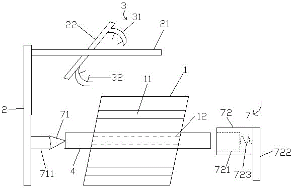
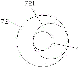
[0028] Such as figure 1 with figure 2 As shown in the figure, an oil cylinder cylinder deformation correction device that can detect and correct simultaneously, which includes a conveying track 1, an arc-shaped groove 11, a detection and correction station 12, a lifting column 2, a horizontal slide rail 21, and a cross bar 22 , coaxiality detection device 3, arc block 31, displacement sensor 32, oil cylinder barrel 4, ellipticity correction device 7, positioning plug gauge 71, telescopic cross bar 711, correction head 72, correction sleeve 721, right sliding column 722 and spring 723 and other main technical features.

[0029] The invention relates to a device for correcting the deformation degree of an oil cylinder cylinder which can be detected and corrected simultaneously, comprising a conveying track, a lifting colu...


PUM


Abstract

This application discloses a cylinder deformation correction device that can detect and correct simultaneously, including a conveying track, a lifting column, a coaxiality measuring device, an ellipticity correcting device, and a PLC; a detecting and correcting station is provided on the conveying track The coaxiality measurement device includes two arc blocks and at least two displacement sensors; the ellipticity correction device includes a telescopic cross bar, a positioning plug gauge, a correction head, a correction sleeve and a right sliding column; the positioning plug gauge can be extended into the correction Inside the cylinder of the oil cylinder on the station; the correction head is fixed on the left side of the right sliding column, the correction head is cylindrical and can rotate axially; the correction head is equipped with a correction sleeve, which is also cylindrical and It can rotate freely in the radial direction; the oil cylinder barrel at the correction station can be freely inserted into the correction sleeve. The application can automatically detect the degree of deformation of the oil cylinder barrel and automatically correct and detect the oil cylinder barrel with a deviation in the degree of deformation, greatly improving the product qualification rate and reducing production costs.

Description

technical field [0001] The application relates to an auxiliary inspection device in the production process of an oil cylinder, in particular to an equipment for correcting the degree of deformation of the cylinder barrel of an oil cylinder which can perform detection and correction simultaneously. Background technique [0002] During the production process of the oil cylinder, there is a high requirement for the coaxiality of the left and right ends of the cylinder. For a longer cylinder, deformation, ellipse or left and right misalignment are more likely to occur during production. Therefore, in the production process, it is necessary to detect the coaxiality of the cylinder. Most of the existing methods are manual visual inspection, the detection rate is low, and the detection has been missed. There is also a method of using the left and right ends of the plug gauge to carry out the plug sleeve, but the detection is cumbersome, the workload is large, and the specific data ...

Claims


Application Information

Patent Timeline
IPC IPC(8): G01B5/20G01B21/24
CPCG01B5/201G01B21/24
Inventor 谷香梅
Owner 谷香梅
Learn More