Method for resisting magnetic interference

A technology of magnetic interference and interference time, applied in the directions of measurement devices, instruments, surveying and navigation, etc., can solve the problems of inaccurate heading angle measurement, weakening heading angle measurement accuracy, and inaccurate MEMS magnetometer heading angle measurement, etc. Guarantee measurement accuracy, reduce interference, and avoid the effect of divergence

Active Publication Date: 2016-10-12
JIYI ROBOT SHANGHAI
View PDF6 Cites 18 Cited by
  • Summary
  • Abstract
  • Description
  • Claims
  • Application Information

AI Technical Summary

Problems solved by technology

[0003] When the MEMS attitude system is applied to micro-sized unmanned aerial vehicles, its working environment is mainly in the low-altitude area, and the integrated MEMS magnetometer in the system is extremely susceptible to the interference of the local magnetic field on the ground and the magnetic field of the airborne motor, which leads to the measurement of the heading angle. Inaccurate
General magnetometer calibration methods include hardware calibration and software calibration methods, such as software calibration methods such as least squares fitting or best ellipse fitting compensation, all of which have a positive impact on the magnetic intensity when the earth's magnetic field is fixed or undisturbed. When the magnetometer is calibrated by the magnetic field, the conventional calibration compensation method will not be able to eliminate the measurement error of the heading angle caused by the interference
Therefore, in view of the problem that the magnetometer is disturbed by the magnetic field and the heading angle measurement is inaccurate, it is necessary to study an anti-magnetic field interference method for the MEMS magnetometer, so as to weaken or effectively control the heading angle measurement accuracy of the MEMS attitude system caused by the magnetic field interference. Impact

Method used


Image

  • Method for resisting magnetic interference
  • Method for resisting magnetic interference
  • Method for resisting magnetic interference

Examples


Embodiment 1

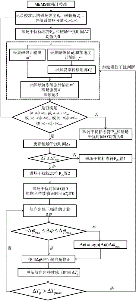
[0032] like figure 1 As shown, a specific implementation method of anti-magnetic interference:

[0033] Step 1. In the initial working stage of the MEMS attitude system, when there is no magnetic field interference, calibrate the MEMS magnetometer, and record the calibrated magnetic field strength B 0 , magnetic inclination δ 0 , and the magnetic field component of the navigation system The magnetic field interference designator P dis set to 0.

[0034] Step 2. Collect the magnetometer output of the MEMS attitude system at a certain moment Gyroscope output and accelerometer output The superscript b stands for machine system.

[0035] Step 3. Output from gyroscope and accelerometer output and the attitude transfer matrix at the previous moment Calculate the current moment attitude transition matrix where n represents the Department of Geography.

[0036] Step 4. According to the magnetometer output and the current moment attitude transfer matrix Computin...


PUM


Abstract

The invention relates to the field of resisting magnetic interference, in particular to a method for resisting magnetic interference. The method includes that magnetic-field strength changing, magnetic inclination changing and magnetic-field component changing of a geographic system are used at the same to judge whether magnetic-field interference exists or not, so that whether the magnetic-field interference exists or not can be judged more accurately; when a magnetic field has the magnetic-field interference and the magnetic-field interference lasts for a long time, course angle divergence caused by solely using a gyroscope for integral computation of a course angle for a long time is avoided; under this circumstance, magnetometer data are recorded and utilized to correct the course angle, so that the course angle divergence is avoided; when the magnetic field has the magnetic-field interference and the magnetic-field interference lasts for a long time, due to the course angle correcting process, interference of the magnetic-field interference on course angle measuring accuracy can be effectively weakened and controlled, and the measuring accuracy of the course angle is guaranteed.

Description

technical field [0001] The invention relates to the field of anti-magnetic interference, in particular to a method for anti-magnetic interference. Background technique [0002] In the MEMS attitude measurement system, only the inertial measurement unit composed of MEMS accelerometer and MEMS gyroscope is used. Due to the angular velocity drift of the gyroscope and the lack of observation and correction information of the heading angle, the output accuracy of the heading angle cannot meet the long-term requirements of the attitude measurement system. time precision requirements. Therefore, in recent years, the MEMS attitude reference system composed of magnetometer and inertial measurement unit has been widely researched and applied, especially in micro UAVs. The MEMS attitude reference system is a sensing system that is composed of a mutually orthogonal three-axis gyroscope, a three-axis accelerometer, and a three-axis magnetometer, and accurately measures space attitude th...

Claims


Application Information

Patent Timeline
Patent Type & Authority Applications(China)
IPC IPC(8): G01C21/16G01C21/20
CPCG01C21/165G01C21/20
Inventor 杭义军邢丽贾文峰吕印新
Owner JIYI ROBOT SHANGHAI
Why Eureka
Try Eureka