
False target identification method based on angular scintillation forwarding

A corner flickering and forwarding technology, applied in radio wave measurement systems, instruments, etc., can solve the problems of complex electromagnetic environment of radar operation, and achieve the effect of good adaptability and application range

Active Publication Date: 2018-05-18
NAT UNIV OF DEFENSE TECH
View PDF3 Cites 0 Cited by
  • Summary
  • Abstract
  • Description
  • Claims
  • Application Information

AI Technical Summary

Problems solved by technology

[0002] With the rapid development of new electronic jamming technology, advanced electronic jamming measures and equipment continue to emerge, resulting in the increasingly complex working electromagnetic environment faced by modern radars

Method used


Image

  • False target identification method based on angular scintillation forwarding
  • False target identification method based on angular scintillation forwarding
  • False target identification method based on angular scintillation forwarding

Examples


Embodiment Construction

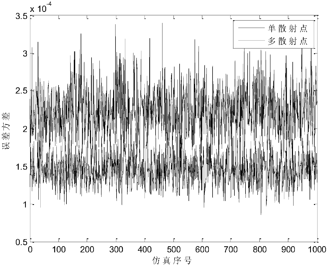
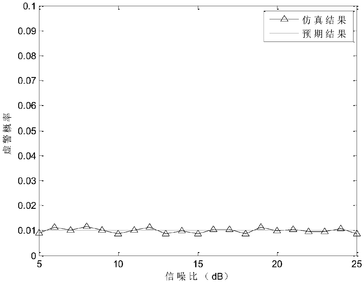
[0048] This method is applicable to various tracking radars. combined with figure 1 -5, the specific steps and effects of this method will be further explained below. The main steps are:

[0049] Step 1: First set the simulation parameters: use a ratio-amplitude monopulse antenna with a beam width of 2°, a beam offset angle of 1°, and transmit signals using chirp signals with a pulse width of 1.6×10 -4 s, the pulse repetition interval is 1.6×10 -2s, the transmitter peak power is 2×10 5 W, the emission frequency is 5×10 9 Hz with a bandwidth of 10 6 Hz, the target RCS is 5.

[0050] Step 2: Perform matched filtering on the received signal. The matched filtering uses the Hamming window, and the sampling frequency after the matched filtering is 4×10 6 MHz.

[0051] Step 3: Obtain the detection threshold according to the set false alarm probability, then use the echo signal to obtain the output of the detector, perform threshold judgment, and finally obtain the detection r...


PUM


Abstract

The invention relates to a repeating false target discriminating method based on angular glint. The method is characterized by establishing an angular glint statistical model according to a monopulse amplitude-comparing angle measurement method and performing correct discrimination by analyzing a difference between the azimuth error variances of an authentic target and a repeating false target and by using a Neyman-Pearson theorem and a generalized likelihood ratio test (GLRT) method, and comprises a step 1 of establishing angular glint statistical model according to the monopulse amplitude-comparing angle measurement method; a step 2 of estimating the parameter of angular observations in order to prepare for further target detection; a step 3 of acquiring a detection threshold according to a set false alarm probability, and then obtaining a detector output by using an echo signal in order to determine a threshold and finally obtain a detection result.

Description

【Technical field】 [0001] The invention belongs to the traditional radar target detection field, and specifically relates to the anti-active deceptive interference detection technology under the current tracking radar system. Furthermore, it is based on the premise that the real target is multi-feed radiation and the forwarding false target is regarded as a single point radiation source. By using the inherent characteristic of the extended target angle flicker, the angle measurement error variance of the real target and the forwarding false target is analyzed. difference, a forwarding false target detection method is proposed. 【Background technique】 [0002] With the rapid development of new electronic jamming technology, advanced electronic jamming measures and equipment continue to emerge, resulting in the increasingly complex working electromagnetic environment faced by modern radars. Especially in recent years, the rapid development of forwarding false target jamming bas...

Claims


Application Information

Patent Timeline
Patent Type & Authority Patents(China)
IPC IPC(8): G01S7/41
CPCG01S7/411
Inventor 艾小锋赵锋刘进王俊杰杨建华肖顺平傅其祥顾赵宇徐振海李永祯潘小义
Owner NAT UNIV OF DEFENSE TECH
Learn More