Carrier wave frequency offset compensation method, apparatus and receiving system

A carrier frequency offset and compensation method technology, applied in the field of communication, can solve the problems of easy filtering, narrow passband bandwidth of low-pass filter, wrong carrier frequency offset estimation, etc., and achieves the effect of strong compatibility and simple realization.

Active Publication Date: 2016-02-17
SHANGHAI EASTSOFT MICROELECTRONICS
View PDF5 Cites 17 Cited by
  • Summary
  • Abstract
  • Description
  • Claims
  • Application Information

AI Technical Summary

Problems solved by technology

from figure 2 It can be seen that if the passband bandwidth of the low-pass filter is too narrow, when the carrier frequency offset is large, it is easy to filter out some or even all useful signals, which in turn leads to carrier frequency offset estimation errors
And if the passband bandwidth of the low-pass filter is too wide, such as image 3 As shown, more noise and interference signals will be introduced while capturing effective signals
[0007] It can be seen that the setting of the passband bandwidth of the low-pass filter has certain limitations in the compensation of large carrier frequency offsets. It is difficult for the existing technology to ensure that the low-pass filter can still compensate for large carrier frequency offsets in the low-bandwidth working mode. Partial

Method used


Image

  • Carrier wave frequency offset compensation method, apparatus and receiving system
  • Carrier wave frequency offset compensation method, apparatus and receiving system
  • Carrier wave frequency offset compensation method, apparatus and receiving system

Examples


Embodiment Construction

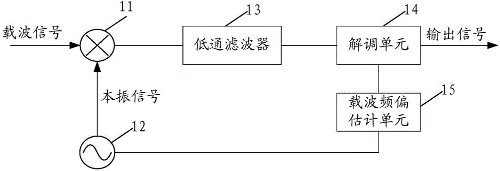
[0044] In the process of transmitting signals in a communication system, there is usually a problem of carrier frequency offset. In order to reduce the impact of carrier frequency offset on receiver performance, the technical solution of the present invention provides a compensation method for carrier frequency offset.

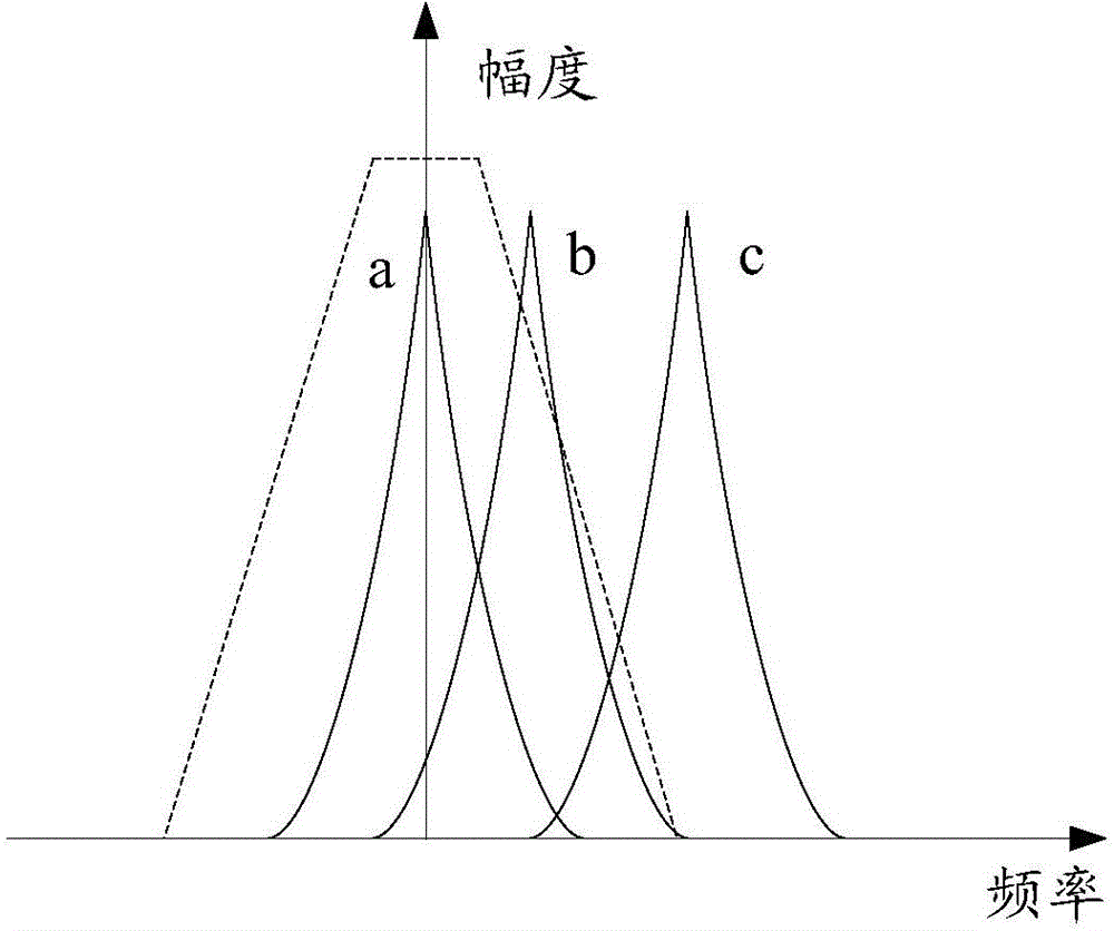
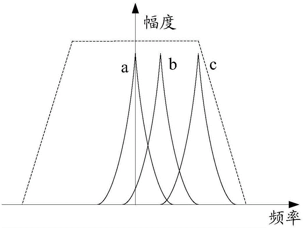
[0045] In the method for compensating the carrier frequency offset provided by the technical solution of the present invention, the estimated value of the carrier frequency offset is determined by means of frequency scanning, so as to realize a rough estimation of the carrier frequency offset. In the process of frequency scanning, calculate the signal strength indicator value (ReceivedSignalStrengthIndicator, RSSI) of the received signal corresponding to each scanning frequency point, that is, the signal energy value of the received signal, based on the received signal corresponding to each scanning frequency point within the frequency scanning range The signal...


PUM


Abstract

A carrier wave frequency offset compensation method, an apparatus and a receiving system are disclosed. The carrier wave frequency offset compensation method comprises the following steps of aiming at each sweeping frequency point in a sweeping frequency scope, calculating a signal intensity indication value of a receiving signal respectively, wherein the sweeping frequency point is used for adjusting a frequency of a receiving-end local oscillator signal; based on the signal intensity indication value and a frequency value of each corresponding sweeping frequency point, determining an estimation value of the carrier wave frequency offset; based on the estimation value of the carrier wave frequency offset, adjusting the frequency of the local oscillator signal so as to realize compensation to the carrier wave frequency offset. Further, through a fine compensation method of the carrier wave frequency offset, the fine compensation is performed on the carrier wave frequency offset after the compensation. Under the condition that the carrier wave frequency offset is large, estimation and compensation can be performed on the carrier wave frequency offset effectively. Under a small bandwidth work mode of a low pass filter, the large carrier wave frequency offset can be compensated. Receiver performance is increased and simultaneously a carrier wave frequency offset compensation scope can be effectively expanded.

Description

technical field [0001] The present invention relates to the field of communication technology, in particular to a carrier frequency offset compensation method and device, and a receiving system. Background technique [0002] In a communication system, when a digital baseband signal is transmitted over a long distance, it is necessary to carry out carrier modulation on the digital baseband signal. The transmitting end in the communication system selects an appropriate modulation method and an appropriate carrier frequency according to the characteristics of the transmission channel, and converts the modulated The digital baseband signal is sent out through the radio frequency transmission circuit. After receiving the signal, the receiving end in the communication system combines with the local carrier through the mixer and performs down-conversion processing, and finally sends the down-conversion signal to the demodulation unit. Perform data demodulation to obtain demodulated...

Claims


Application Information

Patent Timeline
Patent Type & Authority Applications(China)
IPC IPC(8): H04L27/26H04L27/38
Inventor 沈力为王坤陈光胜张晓诗
Owner SHANGHAI EASTSOFT MICROELECTRONICS
Why Eureka
Try Eureka