Wavelength division multiplexer capable of being integrated in CFP and CFP2 standard high-speed transceivers

A technology of wavelength division multiplexer and transceiver, which is applied in the direction of equipment, optical waveguide coupling, light guide, etc., can solve the problems that CWDM devices cannot integrate high-speed transceivers and low cost, and achieve compact arrangement, reduce energy consumption, The effect of reducing the warehouse area

Inactive Publication Date: 2016-10-12
杭州埃戈光电科技有限公司
View PDF4 Cites 16 Cited by
  • Summary
  • Abstract
  • Description
  • Claims
  • Application Information

AI Technical Summary

Problems solved by technology

The 40G/100G high-speed transceiver standard limits the size of the device. For example, the size of the largest transceiver in the IEEE802.3ba standard is only 145mm×82×13.6mm. The size of the traditional 4-channel CWDM: 110×80×1

Method used


Image

  • Wavelength division multiplexer capable of being integrated in CFP and CFP2 standard high-speed transceivers
  • Wavelength division multiplexer capable of being integrated in CFP and CFP2 standard high-speed transceivers
  • Wavelength division multiplexer capable of being integrated in CFP and CFP2 standard high-speed transceivers

Examples


Embodiment 1

[0034] Such as figure 1 and 2 As shown, the assembly process of this embodiment is as follows:

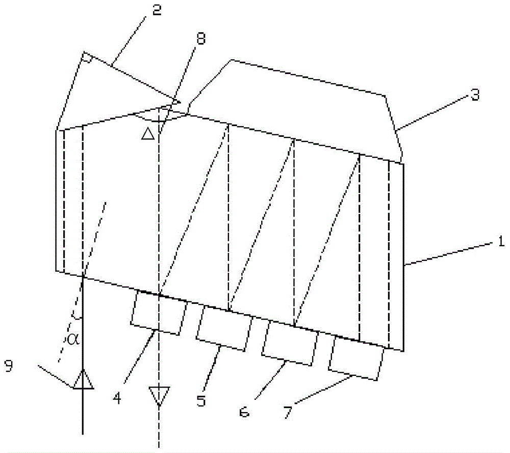
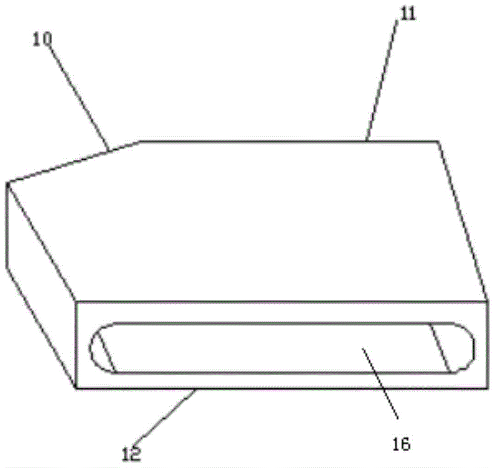
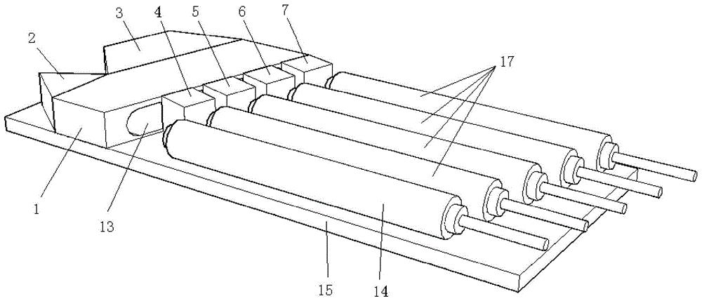
[0035] First, clean the filter holder 1 with alcohol to ensure the cleanliness of the surface. The filter holder 1 is the glass base of the hollow structure 16, and the opposite two sides are provided with openings communicating with the hollow structure 16, and one of the sides with the opening is covered by the filter The bracket is bonded to the plane mirror surface 11 and the filter plate bracket is bonded to the filter plate surface 12. The included angle formed by the filter plate bracket’s bonding plane mirror surface 11 and the filter plate bracket’s bonding filter surface 12 is 167°. In the present embodiment, the rectangular prism 2 The included angle between the side edge and the plane formed by the optical axes of the outgoing light of any two filters is 90°.

[0036] The rectangular prism 2 is bonded to the filter holder bonding filter surface 12 so that the rectangu...

Embodiment 2

[0040] Such as Figure 4 As shown, in this embodiment, except that the arrangement of the rectangular prism 2 and the incident light inlet 13 is different from that of Embodiment 1, the rest of the structure is the same as that of Embodiment 1.

[0041] In the present embodiment, rectangular prism 2 and image 3 Compared with the direction turned 90 degrees, the angle between the side edges of the right-angle prism 2 and the plane formed by the optical axes of the outgoing light of any two filters is 0°, so that the input port 21 of the right-angle prism 2 is located at the filter 4 and the bottom of the filter holder 1, that is, the input collimator 14 is below the four output collimators 17, so that the overall optical component structure is consistent with image 3 The structure is more compact and the size is smaller.


PUM


Abstract

The invention discloses a wavelength division multiplexer which can be integrated into CFP and CFP2 standard high-speed transceivers, which comprises a filter holder and a plurality of filters, and the plurality of filters sequentially transmit light of a set wavelength and reflect the rest of the light to the bottom A filter, the filter holder is provided with an incident light inlet, and also includes a right-angle prism and a plane mirror, all filters and the incident light inlet are installed on the same side of the filter holder, and the right-angle prism and the plane mirror are installed on the filter The other side of the sheet holder is arranged opposite to all the filters. The oblique surface of the rectangular prism refracts the incident light to the nearest filter, and each filter transmits the light of the set wavelength and reflects the light of the remaining wavelengths to the flat mirror behind the flat mirror. Reflected to the next filter; the invention can greatly compress the size of the device, not only can be applied to high-speed transceivers, but also can save production costs, reduce product footprint, and have higher stability than traditional coarse wavelength division multiplexing , with a wide range of applications.

Description

technical field [0001] The invention relates to the technical field of optical fiber communication, in particular to a wavelength division multiplexer which can be integrated into CFP and CFP2 standard high-speed transceivers. Background technique [0002] With the development of optical fiber communication technology, WDM technology makes full use of the huge bandwidth resources of the low-loss optical fiber band. The transmission capacity of an optical fiber is several times or dozens of times higher than that of single-band transmission, which reduces costs and has great application value. and economic value. Since the transmission wavelength of the optical fiber is limited, when arranging optical channels, the shorter the wavelength interval, the more optical channels can be arranged. Therefore, the shorter the wavelength interval, the higher the cost of the wavelength division multiplexing equipment, so in the application, the coarse wavelength division multiplexer (CW...

Claims


Application Information

Patent Timeline
IPC IPC(8): G02B6/293G02B6/34G02B6/42
CPCG02B6/29379G02B6/34G02B6/4286
Inventor 岳学锋徐永明张明月余桂英胡一帆
Owner 杭州埃戈光电科技有限公司
Why Eureka
Try Eureka