3D display panel, preparation method thereof, and 3D display device

A display panel and liquid crystal display panel technology, applied in the direction of optical components, optics, instruments, etc., can solve the problems affecting the firmness of the spacer glass and the display panel, poor light uniformity, and affecting the 3D display effect, so as to improve the firmness and The effect of the uniformity of the outgoing light

Active Publication Date: 2016-10-12
BOE TECH GRP CO LTD
View PDF7 Cites 2 Cited by
  • Summary
  • Abstract
  • Description
  • Claims
  • Application Information

AI Technical Summary

Problems solved by technology

[0005] However, during the UV curing process of the UV glue, the UV glue located under the light-shielding pattern cannot be cured, thus affecting the firmness of the fixation between the spacer glass and the display panel, and the spacer glass and the display panel are prone to relative displacement. As a result, the parallax barrier cannot be precisely matched with the 2D display panel, and the light uniformity is poor, which affects the 3D display effect.

Method used


Image

  • 3D display panel, preparation method thereof, and 3D display device
  • 3D display panel, preparation method thereof, and 3D display device
  • 3D display panel, preparation method thereof, and 3D display device

Examples


Embodiment 1

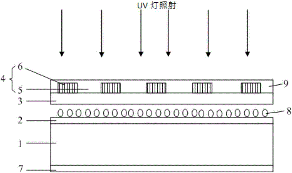
[0037] figure 1 This is a schematic structural diagram of a 3D display panel provided in the first embodiment of the present invention, such as figure 1 As shown, the 3D display panel includes: a 2D display panel 1, a first polarizer 2, a spacer substrate 3, and a polarizing layer 4. The first polarizer 2 is located on one side of the 2D display panel 1, and the spacer The bottom 3 is located on the side of the first polarizer 2 facing away from the display panel, and the polarizing layer 4 is located on the side of the spacer substrate 3 facing away from the first polarizer 2. The polarizing layer 4 includes: a number of light-transmitting regions 5 and a number of polarizing regions. The light-transmitting regions 5 and the polarizing regions are arranged alternately and in parallel. Each polarizing region is provided with a polarizing structure 6 and all the polarizing structures 6 are arranged in parallel; The sheet 2 has a first polarization axis, the polarization structure...

Embodiment 2

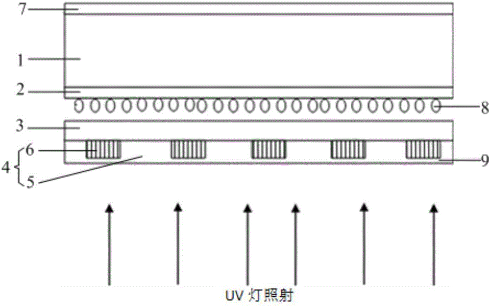
[0050] image 3 It is a schematic structural diagram of a 3D display panel provided in the second embodiment of the present invention, such as image 3 As mentioned, the difference from the first embodiment above is that the 2D display panel 1 in this embodiment can only be a liquid crystal display panel, and the first polarizer 2 is attached to the light incident side of the 2D display panel 1 at this time.

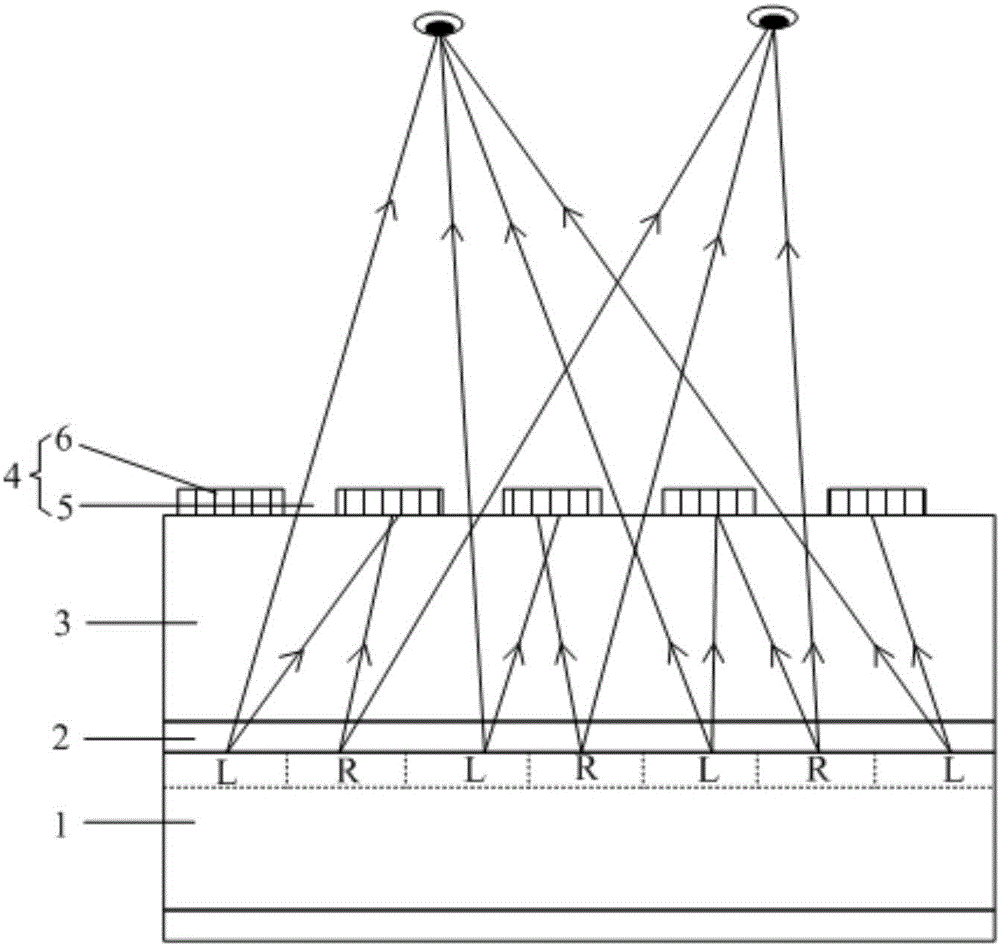
[0051] Figure 4 for image 3 The light path diagram of the 3D display panel shown in 3D display, such as Figure 4 As shown, when the 3D display panel provided in this embodiment performs display, the light generated by the backlight source (not shown) will first be emitted to the polarizing layer 4. Wherein, the light directed to the light-transmitting area 5 of the polarizing layer 4 will be directly transmitted from the light-transmitting area 5, and pass through the spacer substrate 3, the first polarizer 2 and the 2D display panel 1 in sequence, and be directed to the e...

Embodiment 3

[0056] Figure 5 This is a flowchart of a method for manufacturing a 3D display panel provided in the third embodiment of the present invention, such as Figure 5 As shown, the preparation method is used to prepare the 3D display panel in the foregoing embodiment 1 and embodiment 2, and the preparation method includes:

[0057] Step 101: Prepare a 2D display panel, and arrange a first polarizer on one side of the 2D display panel.

[0058] In step 101, an existing liquid crystal display panel manufacturing process or an OLED display panel manufacturing process can be used to prepare a 2D display panel. Wherein, when the 2D display panel is an OLED display panel, the first polarizer needs to be attached to the light-emitting side of the OLED display panel; when the 2D display panel is a liquid crystal display panel, it is necessary to attach the first polarizer on both sides of the liquid crystal display panel. The first polarizer and the second polarizer are attached, wherein the...


PUM


Abstract

The invention discloses a 3D display panel, a preparation method thereof, and a 3D display device. The 3D display panel comprises a 2D display panel, a first polarizer, a spacer substrate, and a polarizing layer. The first polarizer is at one side of the 2D display panel. The spacer substrate is at one side of the first polarizer opposite to the display panel, and the polarizing layer is at one side of the spacer substrate opposite to the first polarizer. The polarizing layer comprises a plurality of transparent areas and a plurality of polarizing areas, and the transparent areas and the polarizing areas are alternately arranged in parallel. Each of the polarizing areas is provided with a polarizing structure, and all polarizing structures are arranged in parallel. The first polarizer has a first polarizing shaft, the polarizing structures comprise second polarizing shafts, and the first polarizing shaft is perpendicular to the second polarizing shafts. According to the technical scheme of the invention, the naked-eye 3D display can be realized, when UV glue is used to fix the first polarizer and space glass, the solidification of each area in the UV glue can be ensured, and thus the firmness of fixation between the space glass and the display panel and the uniformity of emitted light are improved.

Description

Technical field [0001] The present invention relates to the field of display technology, in particular to a 3D display panel, a preparation method thereof, and a 3D display device. Background technique [0002] The display devices used in daily life generally adopt two-dimensional display, which cannot intuitively express the depth information of the scene. With the development of computer information technology and display technology, three-dimensional display technology has become a research focus in the display field. The working principle of three-dimensional (3D) display technology is: for the same scene, the viewer’s left eye and right eye receive images respectively, and the position difference caused by the interpupillary distance between the viewer’s eyes, The retina of the right eye will show two slightly different images. This difference is called "binocular parallax". The two different images form a pair of "stereoscopic image pairs". After the fusion of the visual ...

Claims


Application Information

Patent Timeline
Patent Type & Authority Applications(China)
IPC IPC(8): G02B27/22G02B27/26G02B30/25
CPCG02B30/25G02B30/27
Inventor 王英涛武乃福
Owner BOE TECH GRP CO LTD
Why Eureka
Try Eureka