
Collimation backlight source and display device

A technology of backlight and light source, applied in the field of collimated backlight and display device, can solve the problems of unable to realize collimated light exit, destroying total reflection of incident light, etc.

Inactive Publication Date: 2016-10-12
BOE TECH GRP CO LTD
View PDF5 Cites 11 Cited by
  • Summary
  • Abstract
  • Description
  • Claims
  • Application Information

AI Technical Summary

Problems solved by technology

[0004] At present, the existing backlight technology is mainly to set a grid pattern on the bottom surface of the light guide plate of the side-illuminated backlight. The total reflection in the light plate realizes the exit of light from the light guide plate, but the light exit direction is divergent, and the exit of collimated light cannot be realized

Method used


Image

  • Collimation backlight source and display device
  • Collimation backlight source and display device
  • Collimation backlight source and display device

Examples


Embodiment 1

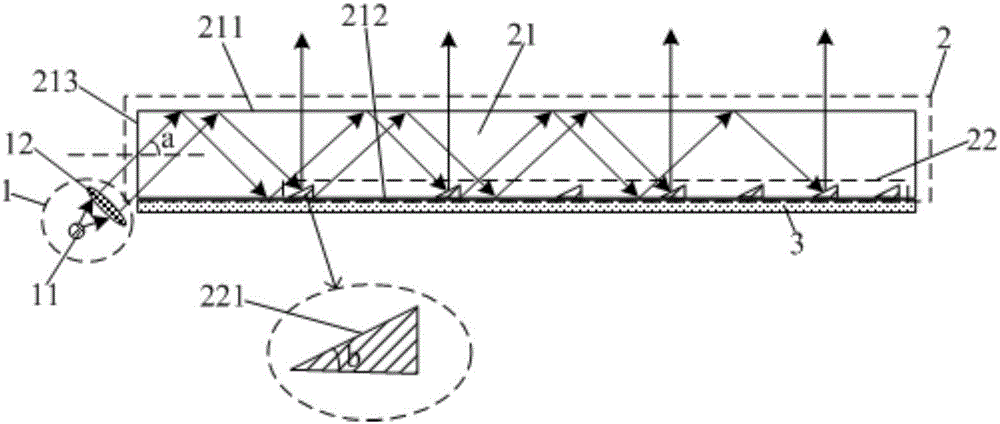
[0030] This embodiment provides a collimated backlight, such as figure 1 As shown, it includes a parallel light providing unit 1, and also includes a dimming unit 2. The parallel light providing unit 1 is located on the light incident side of the dimming unit 2, and is used to provide parallel incident light to the dimming unit 2; the dimming unit 2 is used for The direction of the parallel incident light is adjusted so that the collimated light is emitted from the light exit side.

[0031] By setting the dimming unit 2, the light output direction of the parallel incident light can be adjusted, and the collimated light can be emitted from the light output side, so that the collimated backlight can provide the collimated light, and then provide anti-peeping display for the display device. technical guarantee.

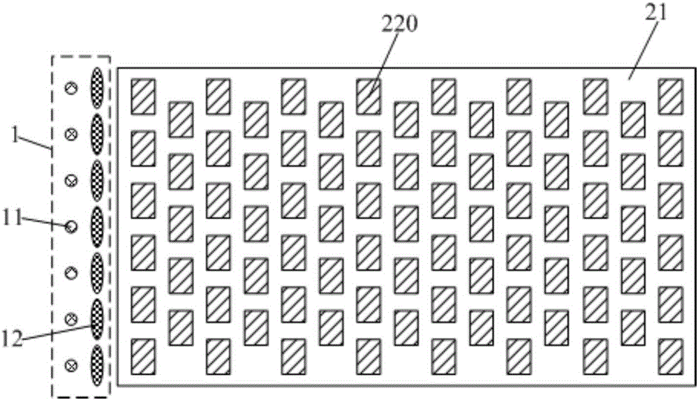
[0032] In this embodiment, the dimming unit 2 includes a light guide plate 21 and a reflective structure 22, the reflective structure 22 is arranged on the bottom surfa...

Embodiment 2

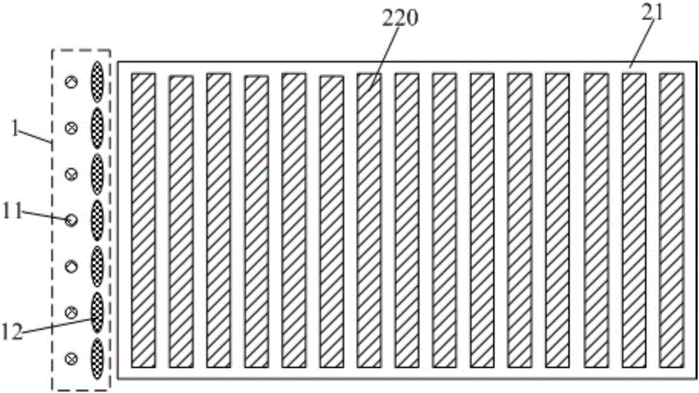
[0043] This embodiment provides a collimated backlight source. The difference from Embodiment 1 is that Figure 4 As shown, the substructure 220 is a reflective plate.

[0044] Other structures and settings of the collimated backlight in this embodiment are the same as those in Embodiment 1, and will not be repeated here.

[0045] Beneficial effects of embodiment 1-2: the collimated backlight provided by embodiment 1-2 can adjust the light output direction of parallel incident light by setting the dimming unit, so that the collimated light can be emitted from the light output side, so that the The collimated backlight realizes the provision of collimated light, thereby providing a technical guarantee for the anti-peeping display of the display device.

Embodiment 3

[0047] This embodiment provides a display device, including the collimated backlight source in any one of Embodiments 1-2.

[0048] By adopting the collimated backlight in any one of the embodiments 1-2, the display device can realize display facing different directions, so that the display device can realize anti-peeping display.

[0049] The display device provided by the present invention can be any product or component with a display function such as a liquid crystal panel, an OLED panel, a liquid crystal TV, an OLED TV, a monitor, a mobile phone, a navigator, and the like.


PUM


Abstract

The invention provides a collimation backlight source and a display device. The collimation backlight source comprises a parallel light providing unit and further comprises a light adjusting unit. The parallel light providing unit is located on the light inlet side of the light adjusting unit and used for providing parallel incident light for the light adjusting unit. The light adjusting unit is used for carrying out direction adjustment on the parallel incident light so that collimated light can be transmitted out of the light outlet side of the light adjusting unit. According to the collimation backlight source, by arranging the light adjusting unit, light outlet direction adjustment can be carried out on the parallel incident light so that the collimated light can be transmitted out of the light outlet side of the light adjusting unit; thus, the collimation backlight source can provide collimated light, and accordingly a technical guarantee is provided for anti-peep display of a display component.

Description

technical field [0001] The present invention relates to the field of display technology, in particular to a collimated backlight source and a display device. Background technique [0002] With the rapid development of flat panel display technology, its display range and application scenarios are constantly expanding. The application scenario of the anti-peep display came into being. In this scenario, the anti-peep display can provide the observer with a sufficiently private viewing experience, greatly improving its private display effect in the special display field. [0003] Since the backlight provided by the collimated backlight can be emitted in a specific direction, it is usually necessary to provide the display panel with a collimated backlight in anti-peeping display products. [0004] At present, the existing backlight technology is mainly to set a grid pattern on the bottom surface of the light guide plate of the side-illuminated backlight. The total reflection in...

Claims


Application Information

Patent Timeline
Patent Type & Authority Applications(China)
IPC IPC(8): G02F1/13357G02B6/00F21S8/00F21V7/00F21V5/04
CPCF21S8/00F21V5/04F21V7/00G02B6/0055G02F1/133605G02F1/133606G02F1/133607
Inventor 马新利陈小川杨亚锋张粲王维王灿谭纪风高健
Owner BOE TECH GRP CO LTD
Learn More