Spiral surface forming machining method

A technology of forming processing and helical surface, applied in the direction of digital control, electrical program control, etc., can solve the problem that the processing of the helical surface section cannot be guaranteed, and achieve the effect of reducing interference, improving processing accuracy, and improving profile accuracy.

Active Publication Date: 2016-10-12
CHONGQING UNIV
View PDF5 Cites 7 Cited by
  • Summary
  • Abstract
  • Description
  • Claims
  • Application Information

AI Technical Summary

Problems solved by technology

[0004] In the case that the forming processing path has been given, the accuracy of the helicoid is determined by the profile accuracy of the forming tool. During processing, once the profile arc of the forming tool is located in the solid body of the workpiece to be processed, interference will occur. The tool will cut off the part of the workpiece to be processed that should not be cut, so that the required helical section cannot be guaranteed to be processed

Method used


Image

  • Spiral surface forming machining method
  • Spiral surface forming machining method
  • Spiral surface forming machining method

Examples


Embodiment Construction

[0028] The present invention will be further described in detail below in conjunction with the accompanying drawings.

[0029] In specific implementation, such as Figure 1 to Figure 5 As shown, a helical surface forming processing method includes the step of selecting a forming tool that matches the helical surface of the workpiece to be processed to perform forming processing on the workpiece to be processed; before processing, the following steps are used to determine the profile of the forming tool:

[0030] 1. Calculation of gear profile

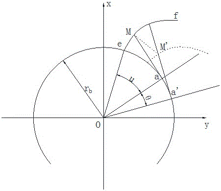
[0031] The coordinate system is established according to the spatial geometric relationship between the spiral surface and the forming tool, and the spatial position relationship and attitude between the forming tool and the spiral surface are determined. Establish the workpiece coordinate system (x, y, z), the grinding wheel coordinate system is (X, Y, Z), and the end section of the involute helicoid is an involute. Such as figure 1...


PUM


Abstract

The invention discloses a spiral surface forming machining method. The method comprises a step according to which a forming cutter matched with the spiral surface of a workpiece to be machined is selected to carry out forming machining on the workpiece to be machined. According to the method, before machining, the theoretical cross-sectional shape of the spiral surface of the workpiece to be machined is determined; the theoretical cross-sectional shape of the forming cutter is determined according to the theoretical cross-sectional shape of the spiral surface of the workpiece to be machined; the actual cross-sectional shape of the spiral surface is obtained according to the theoretical cross-sectional shape of the forming cutter; the actual cross-sectional shape of the spiral surface is compared with the theoretical cross-sectional shape of the spiral surface; if the maximum error of the actual cross-sectional shape of the spiral surface and the theoretical cross-sectional shape of the spiral surface is smaller than the accuracy of the workpiece to be machined, it can be determined that the obtained cross-sectional shape of the forming cutter satisfies requirements, otherwise, the actual cross-sectional shape of the spiral surface is made into a symmetric spiral surface cross-sectional shape relative to the theoretical cross-sectional shape of the spiral surface, and the symmetric spiral surface cross-sectional shape is adopted as a new theoretical cross-sectional shape of the spiral surface; and iterative computation is carried out until the error satisfies the requirements. With the spiral surface forming machining method of the invention adopted, the improvement of the profile accuracy of the forming cutter can be benefitted, the interference of the forming cutter and the workpiece to be machined can be decreased, and the machining accuracy of a gear can be improved.

Description

technical field [0001] The invention relates to the field of mechanical processing, in particular to a method for forming a spiral surface. Background technique [0002] Helicoid is a type of curved surface widely used in mechanical products, such as helical gears, cylindrical end mills and screw rotors, etc., and their surfaces are helicoids. In manufacturing, due to the complex forming of the helicoid, many technical parameters, strong manufacturability requirements, and difficulty in ensuring manufacturing accuracy, the research on its forming principle and processing technology has always been an important research topic in the field of mechanical manufacturing. [0003] There are many ways to process helical surfaces, among which forming processing is very important, such as forming grinding of gears, forming milling of screws, etc. The forming tool for helical surface machining is generally disc-shaped. During forming processing, the profile of the forming tool is tan...

Claims


Application Information

Patent Timeline
Patent Type & Authority Applications(China)
IPC IPC(8): G05B19/19
CPCG05B19/19
Inventor 李国龙娄洋王时龙钟金童钟映寰
Owner CHONGQING UNIV
Why Eureka
Try Eureka