Curved surface machining method and an apparatus thereof

a machining method and machining method technology, applied in the direction of grinding machines, grinding machine components, manufacturing tools, etc., can solve the problems of time required to finish the surface, inability to achieve mass production, and difficulty in achieving a desired curved surface. achieve the effect of improving surface roughness, improving profile accuracy, and improving precision

Inactive Publication Date: 2005-05-05
NAKASHIMA PROPELLER +2
View PDF6 Cites 7 Cited by
  • Summary
  • Abstract
  • Description
  • Claims
  • Application Information

AI Technical Summary

Benefits of technology

[0015] When a high-speed fluid into which an abrasive has been admixed is sprayed onto the surface of a workpiece, an extremely delicate grinding finish can be achieved even with spherical surface machining by reducing the grain size of the abrasive to 1 μm or less and by adjusting the relative position, direction, and angle of the nozzle and the workpiece. As a result, not only can the surface roughness be improved, but a profile accuracy (circularity) can also be improved.
[0016] The present curved surface machining method naturally has such advantages of water jet machining in an abrasive-containing solution that there is no need to supply an abrasive because the abrasive in the abrasive-containing solution is circulated by the high-speed fluid; there is no resulting abrasion or clogging of the nozzle; the running costs are low, so that an economical improvement is achieved; there is no need to stir the solution in order to make the abrasive uniform because the abrasive-containing solution is circulated by the high-speed fluid; and the abrasive and the like can be prevented from scattering since the high-speed fluid is sprayed in a liquid, making it possible to avoid contaminating the surrounding environment.
[0017] Incidentally, special considerations need to be taken for the present machining method when the workpiece is a sphere such as in the head of a bone in an artificial hip joint. More specifically, a water jet is sprayed onto the entire external peripheral surface of the workpiece while rotating the workpiece and varying the relative position of the nozzle and the workpiece. However, the workpiece has different peripheral velocities near the equator and near the poles, and advancing the nozzle or the workpiece at a constant velocity makes the machining amount different, so that the circularity drops. In concrete terms, the machining amount per unit length increases near the poles of a workpiece with a low peripheral velocity, which results in a distorted spherical shape. Accordingly, the advance speed of the table is controlled so that the amount of the sprayed water jet received by the machined surface of the workpiece per unit of time remains constant.

Problems solved by technology
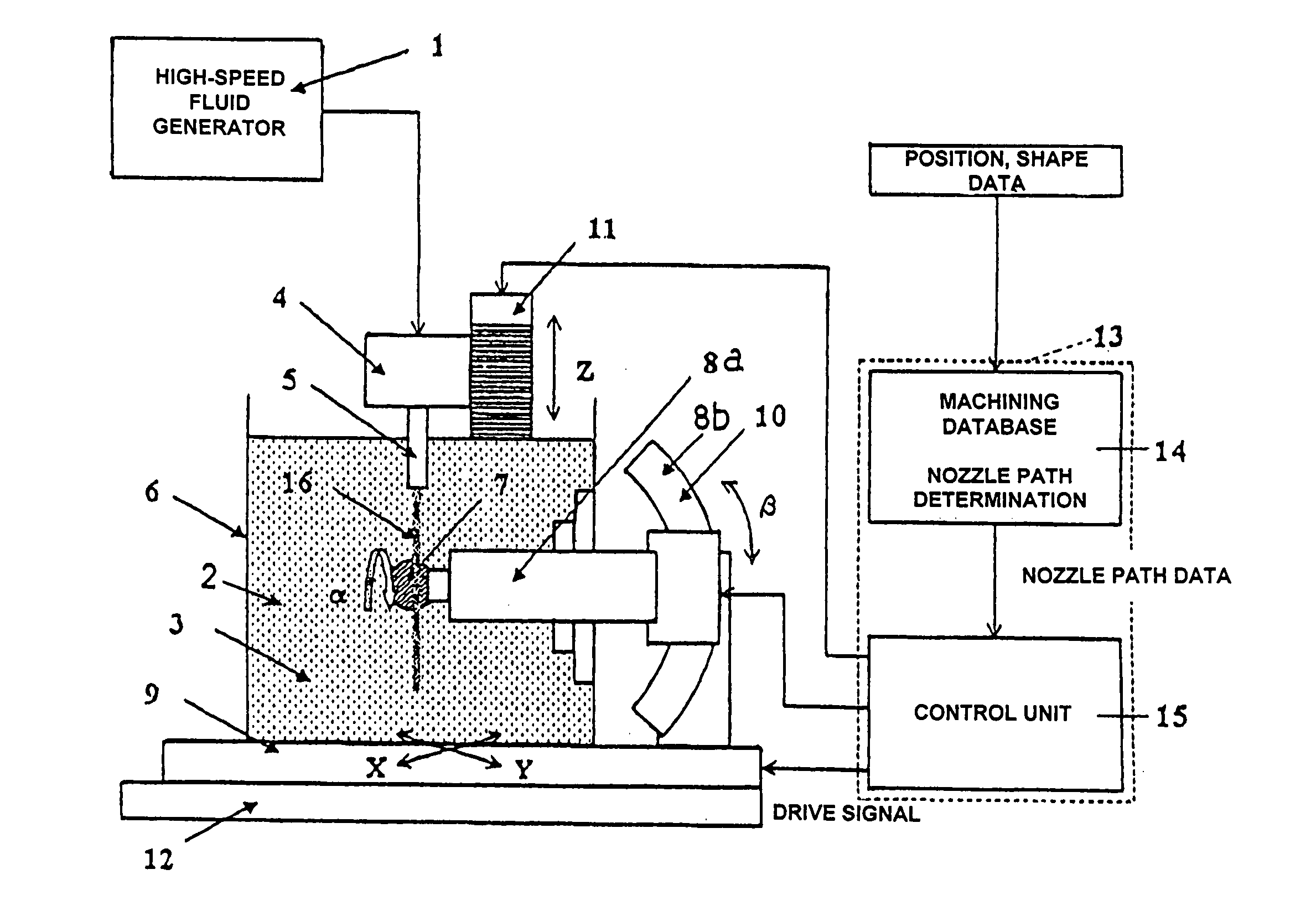
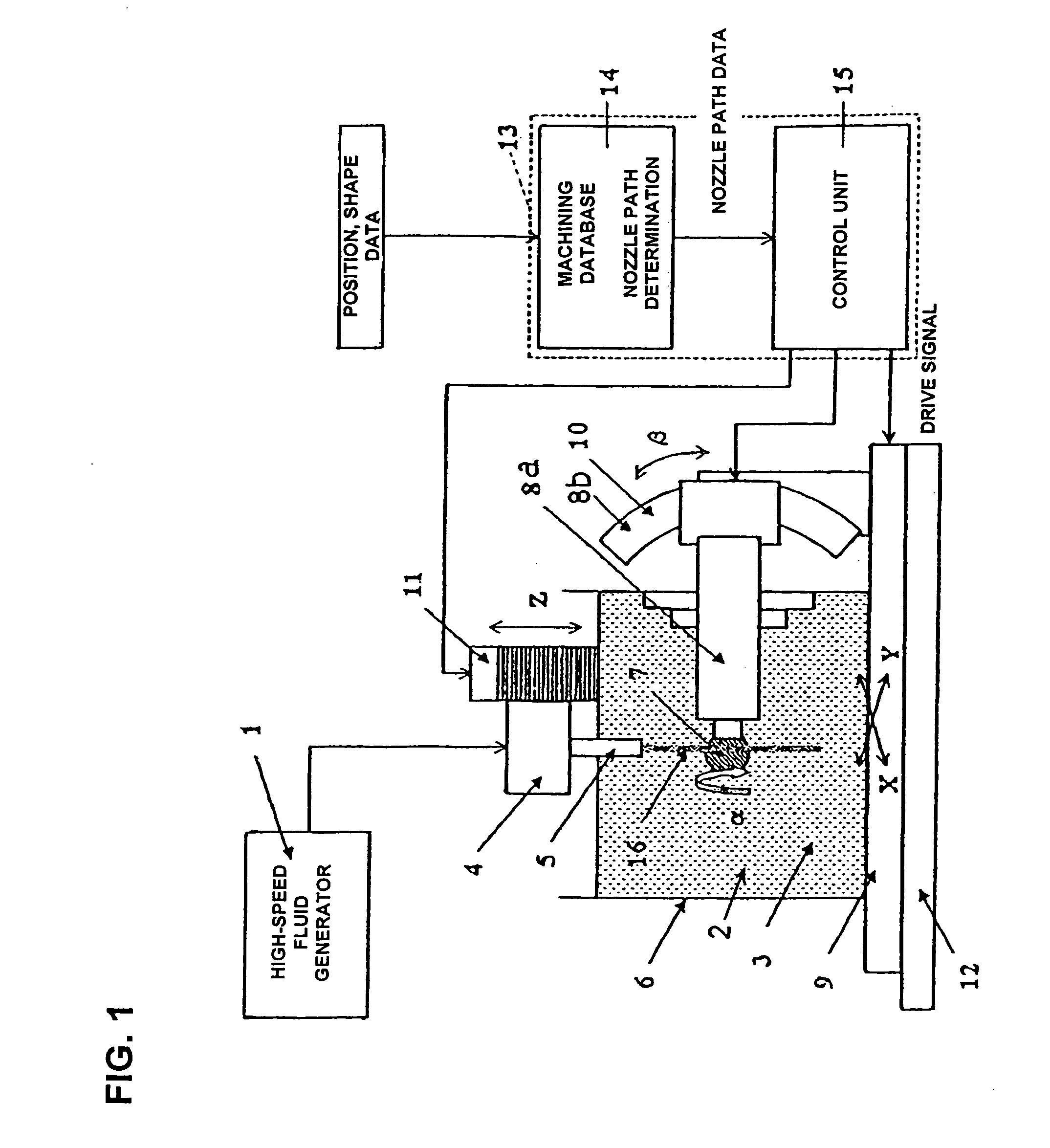
However, finishing a desired curved surface requires a great deal of skill and has not been something that anyone can easily accomplish.
Furthermore, time is required to finish the surface, and mass production has not been deemed feasible.
One method of curved surface machining involves mixing an abrasive into a high-speed fluid and spraying the resulting material onto a machined surface, as seen in Japanese Patent Application Laid-Open (Kokai) No. 2000-158344, but this approach has problems in that the abrasive causes wear and clogging in the nozzle for spraying the high-speed fluid.
Furthermore, a large amount of the abrasive is needed, and the abrasive sometimes scatters into the surroundings.
Consequently, precise machining aimed at improving the surface roughness or dimensional accuracy of a curved surface cannot be accomplished.
Above all, the method in the prior-art example described above causes additional damage on the surface of the workpiece because an abrasive with a grain size of 1 μm or more is used, which is unacceptable even in terms of surface roughness alone.
However, such a control function is insufficient for improving the surface roughness or profile accuracy of a curved surface.

Method used


Image

  • Curved surface machining method and an apparatus thereof
  • Curved surface machining method and an apparatus thereof
  • Curved surface machining method and an apparatus thereof

Examples


embodiment 1

[0041] Test results will be shown for a case in which the curved surface machining apparatus according to the present invention was used to actually perform finishing machining for improving the surface roughness and profile accuracy of the surface of a workpiece with a convex spherical surface. An abrasive dissolved in water was used as the abrasive-containing solution used herein, the head of a bone (22.2 mm in diameter (surface roughness: 0.04 μm Ra)) for a spherical artificial hip joint made of a medical Co—Cr—Mo alloy was used as the workpiece, and a water jet was used as the high-speed fluid.

[0042] The procedure for this test is as follows:

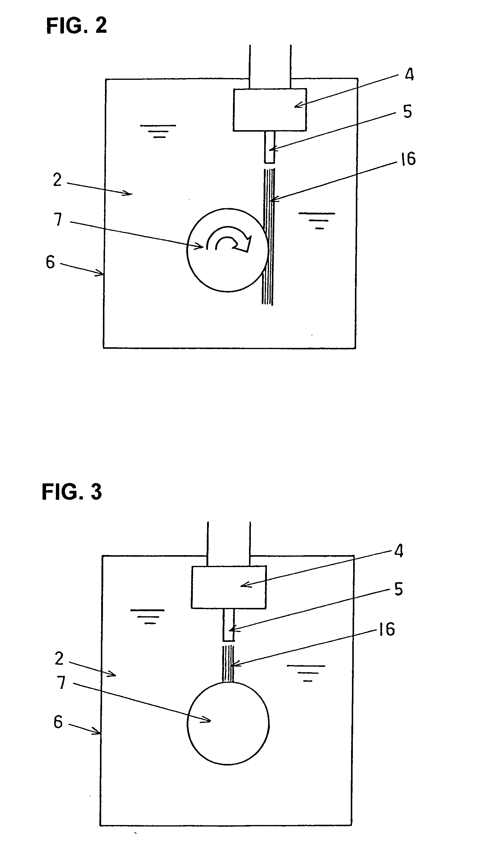
[0043] First, the head of a bone is set on an attachment jig and mounted on a spindle, and the center of the spherical surface formed by the head of the bone is determined. FIG. 4 is an explanatory diagram showing this step as seen from the X-axis direction, and FIG. 5 is an explanatory diagram as seen from the Z-axis direction. The spindl...

embodiment 2

[0052] Next, a method for optimally machining a spherical workpiece such as the head of a bone will be described.

[0053] If the workpiece is spherical, the peripheral velocity of a certain peripheral surface along the Y axis is different depending on the distance (angle) from the equator of the sphere. Therefore, rotating the workpiece at a constant rotational speed or keeping the advance speed of the nozzle constant causes the machining conditions to differ in that portion, so that circularity is sometimes reduced even more. Furthermore, the amount of abrasive in the abrasive-containing solution decreases as the grinding progresses, so the conditions are different at the start and end of machining. Accordingly, machining conditions must be set with this taken into account.

[0054] First, in the case of the advance speed, the amount of the water jet received by the machined surface of the workpiece (the sprayed surface being sprayed with the water jet) per unit of time is designed to...

embodiment 3

[0061] In order to verify the above, with the use of the machining conditions shown in Table 3, an experimentation and simulation were carried out with the method shown below. The circularity of the head of the bone following machining was then measured or the following three cases: [0062] (i) When the advance speed was kept constant at 0.01 mm / s [0063] (ii) When the advance speed was controlled

[0064] (iii) When the advance speed was controlled and the concentration corrected

TABLE 3Nozzle advance speed (mm / s)0.01Nozzle diameter (mm)0.25Abrasive grain size (μm)1.0Initial abrasive concentration (wt %)3.2Standoff distance (mm)8.5Water jet pressure (Mpa)200Rotational speed of workpiece (rpm)3000Abrasive materialGreen silicon carbide

[0065]FIG. 9 shows the results of measuring the circularity shown in the results of (i) through (iii). In the case of (i) above, machining was excessive near the poles of the head of a bone where the advance speed is low, so that the circularity deteriorat...


PUM

PropertyMeasurementUnit
grain sizeaaaaaaaaaa
particle sizeaaaaaaaaaa
surface roughnessaaaaaaaaaa

Abstract

A curved surface machining method that performs finishing of the surface of a workpiece into a curved surface. The method includes the steps of: setting a workpiece in a rotating or stationary state in a water tank filled with an abrasive-containing solution into which an abrasive with a grain size of less than 1 μm has been admixed; and spraying a high-speed fluid in the abrasive-containing solution while a position, direction, and angle thereof is controlled relative to the workpiece, thus grinding and finishing the surface of the workpiece to an intended surface roughness and profile accuracy.

Description

BACKGROUND OF THE INVENTION [0001] 1. Technical Field [0002] The present invention relates to a curved surface machining method and a curved surface machining apparatus, wherein a high-speed fluid is sprayed onto a workpiece in an abrasive-containing solution into which an abrasive has been admixed, and the surface of the workpiece is ground to an intended surface roughness and profile accuracy. [0003] 2. Description of the Related Art [0004] In structural components requiring long-term durability such as artificial joints, for example, the profile accuracy and surface roughness of opposing sliding surfaces have a marked effect on the abrasion resistance of these surfaces. In conventional practice, manual procedures that use a V-type grindstone, a toroid grindstone, or a spherical grindstone have been used in curved surface machining for these spherical surfaces or non-spherical surfaces. However, finishing a desired curved surface requires a great deal of skill and has not been som...

Claims


Application Information

Patent Timeline
Patent Type & Authority Applications(United States)
IPC IPC(8): B24C3/00B24C1/04B24C3/22B24C5/02B24C7/00
CPCB24C1/04B24C7/0007B24C5/02B24C3/22
Inventor MITSUISHI, MAMORUWARISAWA, SHINICHIKURAMOTO, KOUICHIINOUE, TAKAYUKI
Owner NAKASHIMA PROPELLER
Why Eureka
Try Eureka