A compression spring of a snap-in electromagnetic relay

An electromagnetic relay and snap-fit ​​technology, applied in the direction of electromagnetic relays, electromagnetic relay details, relays, etc., can solve problems such as difficult insertion, low assembly efficiency, and difficult shaping, achieve good guiding effects, improve automated assembly, and avoid adverse effects

Active Publication Date: 2018-11-09
XIAMEN HONGFA SIGNAL ELECTRONICS CO LTD
View PDF6 Cites 3 Cited by
  • Summary
  • Abstract
  • Description
  • Claims
  • Application Information

AI Technical Summary

Problems solved by technology

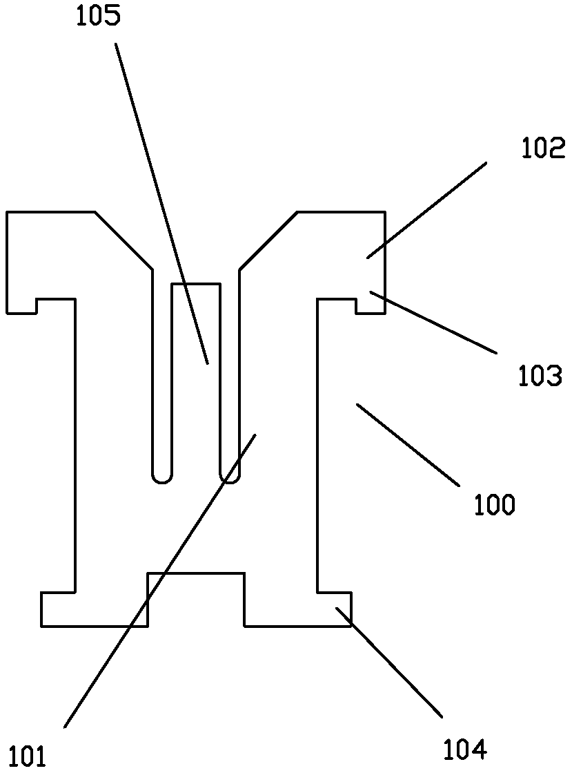
[0003] This compression spring has the following disadvantages in the insertion process: one is that the clamping feet of the compression spring (i.e. the lower side wings 104 of the main sheet body) are sheet-shaped, and the thickness is relatively thin, which is easy to scrape with the plastic slot, so it is not easy to insert , the assembly efficiency is low, and the automatic assembly is difficult. The position accuracy is low and the consistency is poor; in order to improve the above defects, the front end of the pairing position of the compression spring and the plastic slot can be reshaped to remove the punching sharp edge, but the punching sharp edge of the compression spring of the existing product is less than 0.5mm. It is more difficult to shape a larger fillet on the edge, especially it is very difficult to shape a fillet with a radius equivalent to the thickness of the material

Method used


Image

  • A compression spring of a snap-in electromagnetic relay
  • A compression spring of a snap-in electromagnetic relay
  • A compression spring of a snap-in electromagnetic relay

Examples


Embodiment 1

[0045] see Figure 6 to Figure 8As shown, the stage clip of a kind of clapping-type electromagnetic relay of the present invention comprises a main piece body 3 of flat plate shape, and the top of main piece body 3 extends out upper side wing 31 with flat piece mode to both sides, and the terminal end of upper side wing 31 is towards A section of empennage 32 is extended in the form of a flat sheet below, and the lower part of the main sheet body extends a lower wing 33 in a flat sheet manner to both sides, and a tongue sheet 34 forming a certain angle with the plane of the main sheet body is provided in the middle of the main sheet body; The tail fin 32 of the main body is provided with a bending portion 35, so that when the upper wing 31 of the clip spring is inserted into the plastic slot of the relay, the arc surface formed by the bending portion 35 is in contact with the plastic slot of the relay. .

[0046] In this embodiment, the bent portion 35 is an arc structure for...

Embodiment 2

[0054] see Figure 14 to Figure 18 As shown, the stage clip of a clapping type electromagnetic relay of the present invention is different from Embodiment 1 in that the bending portion 35 is located in the middle section of the empennage 32 and is facing away from the tongue of the main body 3. The arc structure 351 protruding from one side of the sheet 34, when the bent part enters the plastic slot, the arc surface of the arc structure 351 contacts the plastic slot 42.

Embodiment 3

[0056] see Figure 19 to Figure 24 As shown, the stage clip of a clapping-type electromagnetic relay of the present invention is different from Embodiment 1 in that the bending direction of the bending portion 35 is different, and the bending portion 35 is the corresponding position of the end of the empennage 32 to the main body 3. The arc structure formed by bending the side away from the tongue piece, when the bent portion 35 enters the plastic slot, the arc surfaces on both sides of the arc structure contact with the plastic slot 42 respectively.

[0057] In this embodiment, the edge of one side 322 of the empennage also has a burr structure formed when the main body is punched out, and the side 322 of the embossment faces away from the tongue 34 . By setting the direction of the burr in advance when the flat piece of the compression spring is stamped, the burr at the position where the compression spring is paired with the plastic slot turns inward in the opposite directi...


PUM


Abstract

The invention discloses a beating type electromagnetic relay pressure spring. The pressure spring comprises a flat-sheet-shaped main sheet body, wherein the upper part of the main sheet body extends towards the two sides in the flat sheet manner to form upper side wings; the tail ends of the upper side wings extend downwardly in the flat sheet manner to form tail wings; the lower part of the main sheet body extends towards the two sides in the flat sheet manner to form lower side wings; a tongue-shaped sheet is arranged in the middle of the main sheet body, wherein a certain inclined angle is formed between the plane of the main sheet body and the tongue-shaped sheet; the tail wings of the main sheet body are provided with bent parts; and when the upper side wings of the pressure spring are mounted in corresponding plastic inserting grooves of the relay, the circular-arc plane formed by the bent parts is in contact with the corresponding plastic inserting grooves of the relay. By adoption of the structure, the consistency in assembling the pressure spring is improved, so that the consistency of the pressing force of the pressure spring is further improved; and meanwhile, the convenience in assembling the pressure spring is improved, so that pollution to the internal environment of the relay is reduced.

Description

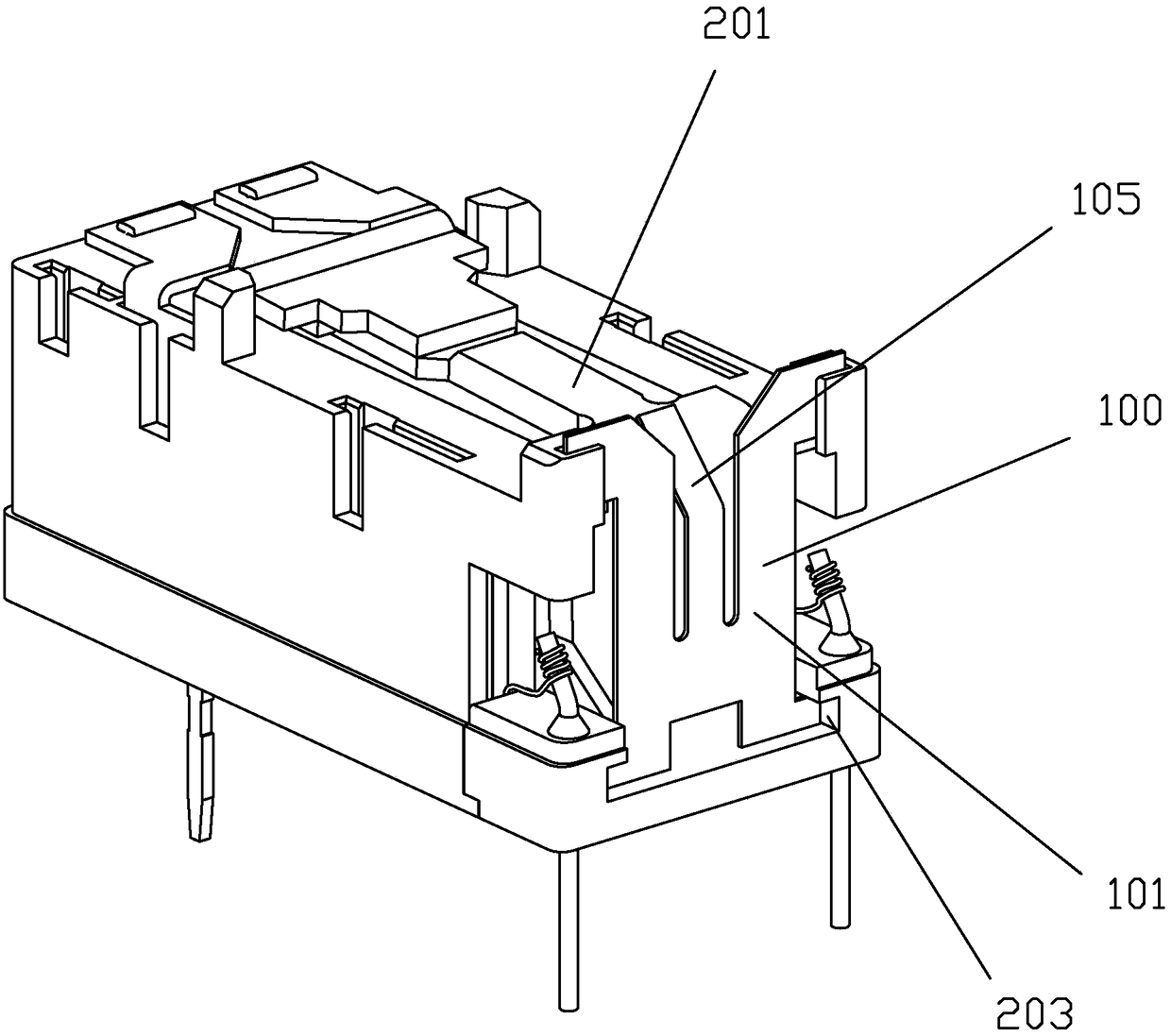
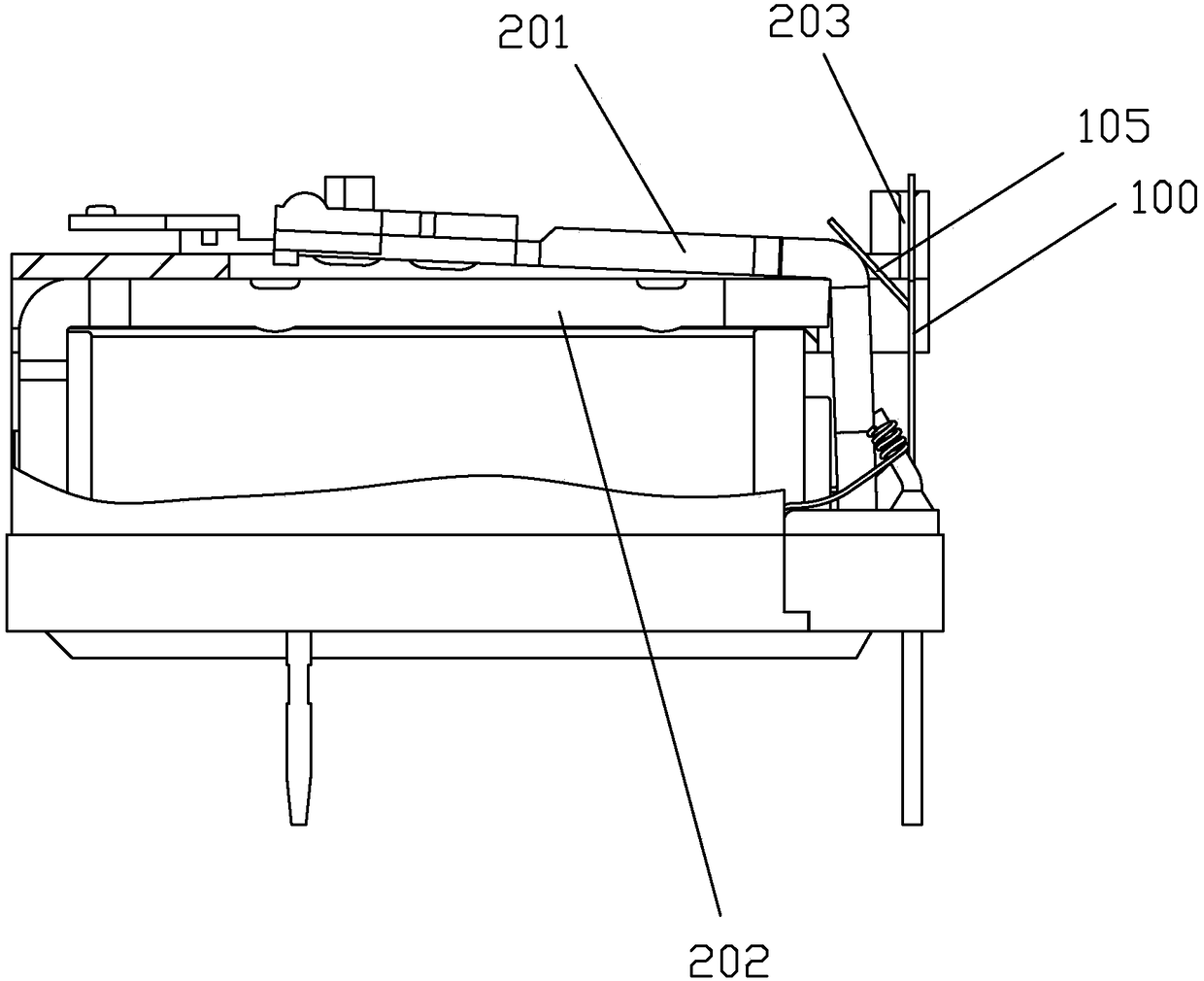
technical field [0001] The invention relates to the technical field of relays, in particular to a compression spring of a snap-in electromagnetic relay. Background technique [0002] A clapping type electromagnetic relay of the prior art such as Figure 1 to Figure 2 As shown, the armature 201 is press-fitted on the knife edge of the yoke 202 by means of the compression spring 100. The compression spring of this clapping type electromagnetic relay is as follows: image 3 , Figure 4 As shown, the compression spring includes a main plate body 101 in the shape of a flat plate. The upper part of the main plate body 101 extends an upper wing 102 in a flat plate manner to both sides, and the end of the upper wing extends downwards with a flat plate form. The lower part of the sheet body extends the lower side wings 104 in the form of a flat sheet to both sides. The middle of the main sheet body 101 is provided with a tongue 105 that forms a certain angle with the plane of the ma...

Claims


Application Information

Patent Timeline
Patent Type & Authority Patents(China)
IPC IPC(8): H01H50/16H01H50/30
CPCH01H50/16H01H50/30
Inventor 潘金国聂福大林佳宾张完郎
Owner XIAMEN HONGFA SIGNAL ELECTRONICS CO LTD
Why Eureka
Try Eureka