Direct-current charging pile

A technology of DC charging pile and charging grab, which is applied to charging stations for charging mobile devices, current collectors, electric vehicles, etc. Operation safety, saving charging cost, good isolation effect

Inactive Publication Date: 2016-10-12
WUHAN ZHONGZHI ELECTRIC
View PDF7 Cites 10 Cited by
  • Summary
  • Abstract
  • Description
  • Claims
  • Application Information

AI Technical Summary

Problems solved by technology

[0003] Due to the high-voltage and high-current output of the currently used charging piles, the device that controls the main circuit consumes a lot. During the charging process, a large amount of heat will be generated, and the control contacts of the main circuit will often be sintered. In an emergency Or after the charging is completed, the main circuit cannot be disconnected, which will damage the battery of the electric vehicle and cause danger

Method used


Image

  • Direct-current charging pile
  • Direct-current charging pile
  • Direct-current charging pile

Examples


Embodiment Construction

[0035] The principles and features of the present invention are described below in conjunction with the accompanying drawings, and the examples given are only used to explain the present invention, and are not intended to limit the scope of the present invention.

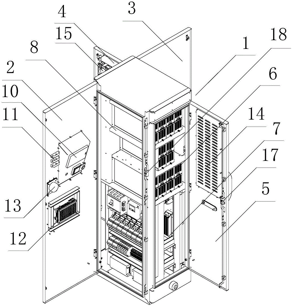
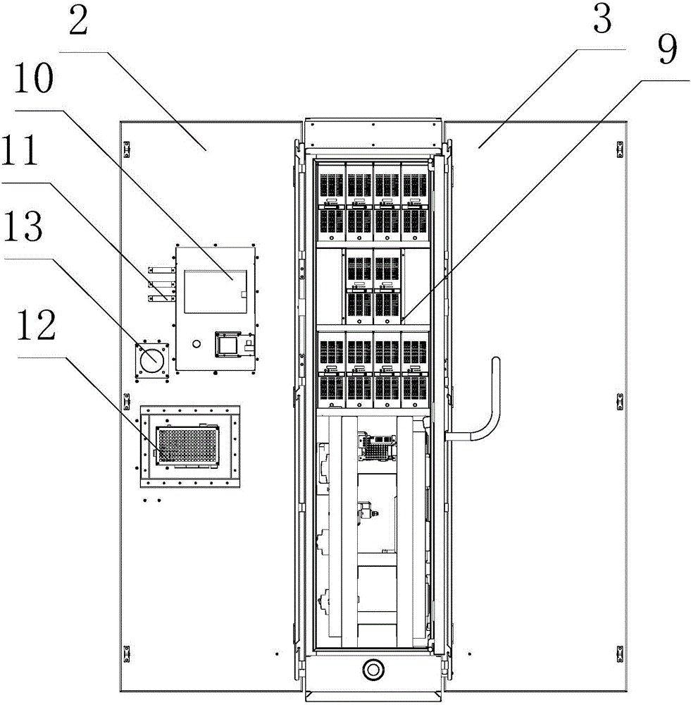
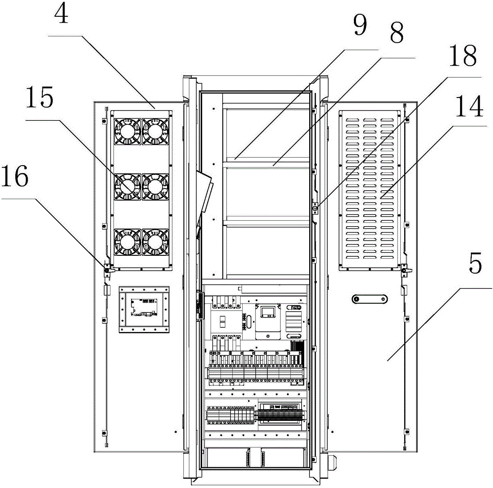
[0036] Such as Figures 1 to 5 As shown, a DC charging pile includes a cabinet body 1 with a rectangular parallelepiped frame structure, and the front, rear, left and right sides of the cabinet body 1 are respectively provided with front cabinet doors 2, Back cabinet door 3, left cabinet door 4 and right cabinet door 5.

[0037] The cabinet 1 is provided with a rectification chamber 6 and a control chamber 7, the rectification chamber 6 is located in the upper part of the cabinet 1, and the rectification chamber 6 is provided with a rectification module, and the control chamber 7 is located in the The lower part of the cabinet body 1, and the control room 7 is provided with primary control equipment and outgoing bu...


PUM


Abstract

The invention relates to a direct-current charging pile, which comprises a cabinet body of a cuboid frame structure. The front side, the rear side, the left side and the right side of the cabinet body are respectively provided with a front cabinet door, a rear cabinet door, a left cabinet door and a right cabinet door, wherein the front cabinet door, the rear cabinet door, the left cabinet door and the right cabinet door are connected with the cabinet body in the rotatable manner. A rectifying chamber and a control chamber are arranged in the cabinet body. The rectifying chamber is located in the upper part of the cabinet body. A rectifying module is arranged in the rectifying chamber. The control chamber is located in the lower part of the cabinet body. A primary control device and a wire outgoing busbar are arranged in the control chamber. A charging gun is hung onto the surface of the cabinet body. According to the technical scheme of the direct-current charging pile, equipment is arranged in different partitions inside the cabinet body, and the rectifying module higher in calorific value is arranged in an independent area. Therefore, the heat can be dissipated conveniently during the charging process, so that the stability of the primary control device is not influenced by the heat radiated by the rectifying module during the charging process. Meanwhile, based on the partitioned arrangement, the isolation effect is better and the operation safety is improved. The electromagnetic interference is reduced and the entire periphery of the cabinet body can be opened. As a result, the cabinet is convenient in installation and maintenance.

Description

technical field [0001] The invention relates to the technical field of mechatronics, in particular to a DC charging pile. Background technique [0002] In the context of the global energy crisis and serious environmental crisis, the Chinese government is actively promoting the application and development of new energy vehicles. Charging piles, as an important supporting infrastructure necessary for the development of electric vehicles, have very important social and economic benefits. Electric vehicle DC charging piles are mainly used in public charging stations, which put forward higher requirements in terms of safety protection, environmental integration, human-computer interaction, and ventilation and heat dissipation. [0003] Due to the high-voltage and high-current output of the currently used charging piles, the device that controls the main circuit consumes a lot. During the charging process, a large amount of heat will be generated, and the control contacts of the m...

Claims


Application Information

Patent Timeline
Patent Type & Authority Applications(China)
IPC IPC(8): H02J7/00
CPCH02J7/0027H02J7/0042Y02E60/10
Inventor 方伟潘拥军李蕾何贤伟张光平陶宏杰孟少华汪文杰
Owner WUHAN ZHONGZHI ELECTRIC
Why Eureka
Try Eureka