

Substation fault information automatic publishing and processing system
A technology of automatic release of fault information, applied in the direction of information technology support systems, electrical components, circuit devices, etc., can solve problems that affect the speed of fault processing, time-consuming and laborious, difficult to recover quickly, etc., to achieve good safety performance, easy to check, The effect of meeting the actual use requirements
- Summary
- Abstract
- Description
- Claims
- Application Information
AI Technical Summary
Problems solved by technology
Method used
Image

Examples
Embodiment Construction
[0020] The content of the present invention will be described below in conjunction with specific embodiments.
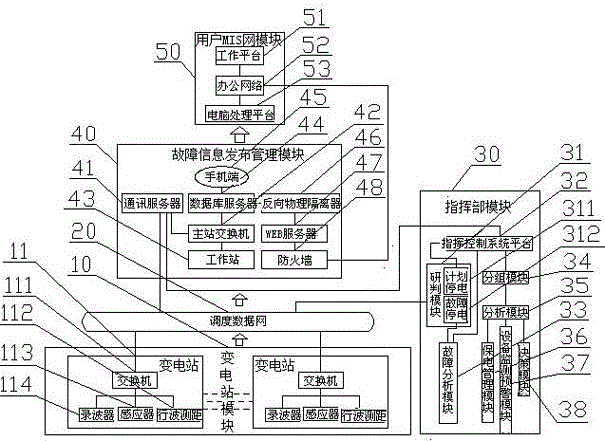
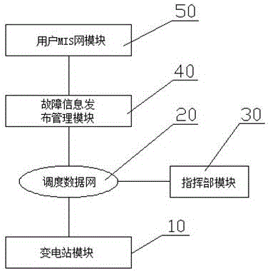
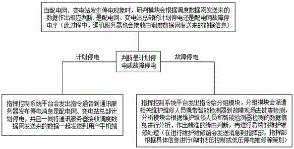
[0021] Such as Figure 1 to Figure 3 As shown, it is a schematic diagram of a substation fault information automatic release and processing system according to the present invention.
[0022] A substation fault information automatic release and processing system according to the present invention includes a substation module 10, a dispatch data network 20, a headquarters module 30, a fault information release management module 40, and a user MIS network module 50. The substation module 10 passes through the dispatch data network 20 is connected with the headquarters module 30 and the fault information release management module 40, and the fault information release management module 40 is connected with the user MIS network module 50. Device 113, traveling wave distance measuring device 112, wave recorder 114, sensor 113 and traveling wave distance measuring device 1...
PUM
 Abstract
Description
Claims
Application Information