Rotor structure for reducing asynchronous motor cage rotor core punching tooth expansion

A squirrel-cage rotor and rotor punching technology, which is applied in the direction of asynchronous induction motors, electrical components, electromechanical devices, etc., can solve the problems affecting the reliability of the rotor, the fracture of the punching plate, and the reliable operation of the motor, so as to avoid the rotor teeth caused by high temperature. The problem of rising, reducing the problem of rotor teeth rising, and avoiding the effect of loose punching

Inactive Publication Date: 2016-10-12
CRRC YONGJI ELECTRIC CO LTD
View PDF7 Cites 2 Cited by
  • Summary
  • Abstract
  • Description
  • Claims
  • Application Information

AI Technical Summary

Problems solved by technology

When the motor is in the working state, the rotor punching is affected by centrifugal force and thermal stress, and the punching with tooth swelling i

Method used


Image

  • Rotor structure for reducing asynchronous motor cage rotor core punching tooth expansion
  • Rotor structure for reducing asynchronous motor cage rotor core punching tooth expansion
  • Rotor structure for reducing asynchronous motor cage rotor core punching tooth expansion

Examples


Embodiment Construction

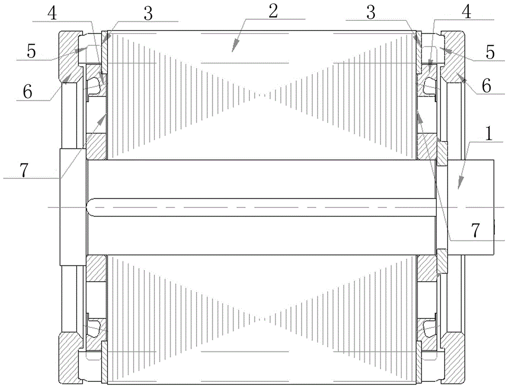
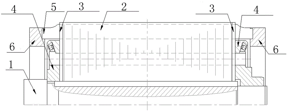
[0018] A rotor structure for reducing tooth expansion of the squirrel-cage rotor core of an asynchronous motor, including a rotor punch 2 sleeved on a rotating shaft 1 and rotating coaxially with the rotating shaft 1, a rotor end plate 3, a rotor pressure ring 4, a guide bar 5 and an end plate ring 6; the rotor end plate 3 presses the outer circle of the rotor punch 2; at the inner circle of the rotor punch 2, there is a gap 7 between the rotor end plate 3 and the rotor pressure ring 4 and the rotor punch 2 ; Rotor pressure ring 4 at the same time pressing the outer round teeth of the rotor punching 2.

[0019] The width and height of the guide bar 5 are 0.1mm smaller than the width and height of the rotor punching slot, the tolerance size of the rotor punching slot is 0~+0.03mm, and the guide bar 5 is -0.05mm~0.

[0020] The guide bar 5 is tightened after being driven into the punching groove of the rotor.

[0021] The gap 7 has a width of 1mm.

[0022] Such as figure 2 A...


PUM

PropertyMeasurementUnit
Widthaaaaaaaaaa

Abstract

The invention relates to a motor rotor structure, in particular to a rotor structure for reducing asynchronous motor cage rotor core punching tooth expansion. The technical problems that an existing motor rotor is prone to quality problems such as rotor tooth expansion and broken teeth, and motor operation is affected are solved. The rotor structure for reducing asynchronous motor cage rotor core punching tooth expansion comprises a rotor punching which is arranged on a rotating shaft in a sleeving mode and rotates around the rotating shaft coaxially, a rotor end plate, a rotor pressing ring, a guide strip and an end ring. The rotor end plate compresses the external circle portion of the rotor punching. On the inner circle portion of the rotor punching, the rotor end plate is matched with the rotor pressing ring, and a gap is reserved between the rotor end plate and the rotor punching; the rotor pressing ring also compresses the outer circle tooth portion of the rotor. According to the motor rotor structure, the problem that rotor tooth expansion is caused by high temperature during welding of the motor rotor guide strip and the end ring is greatly solved, the problem of broken teeth possibly caused in the motor operation is avoided, and the motor operation reliability is improved. The guide strip and the punching are suitable in fit dimension, punching loosening is avoided, and reliability is improved.

Description

technical field [0001] The invention relates to a motor rotor structure, in particular to a rotor structure for reducing tooth expansion of a squirrel-cage rotor iron core of an asynchronous motor. Background technique [0002] When the motor is used as traction power to provide equipment to drive the system to run, it needs to provide power to the system. When the three-phase symmetrical winding of the asynchronous motor stator is connected to the three-phase symmetrical alternating current, an air gap rotating magnetic field is generated. The rotating magnetic field cuts the rotor bar to induce the rotor current, and the rotating magnetic field interacts with the rotor current to generate electromagnetic torque to provide power to the system. In order to ensure that the motor can reliably provide power, the reliability of the rotor structure is the key. The most commonly used motor rotors such as image 3 As shown, it includes six parts: rotor punching plate, rotor end pl...

Claims


Application Information

Patent Timeline
IPC IPC(8): H02K17/16
CPCH02K17/16H02K2213/03
Inventor 霍向飞赵英豪
Owner CRRC YONGJI ELECTRIC CO LTD
Why Eureka
Try Eureka