Self-biasing circuit

A self-biasing and circuit technology, applied to electrical components, generating electrical pulses, and generating pulses, etc., can solve the problem of inability to eliminate the first-order component of coupled noise, and achieve the effect of offsetting limited output impedance and offsetting effects.

Active Publication Date: 2016-10-12
NO 24 RES INST OF CETC
View PDF3 Cites 8 Cited by
  • Summary
  • Abstract
  • Description
  • Claims
  • Application Information

AI Technical Summary

Problems solved by technology

[0004] In view of the shortcomings of the prior art described above, the purpose of the present invention is to provide a self-bias circuit for solving t...

Method used

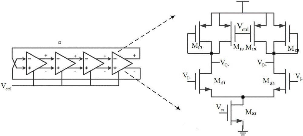
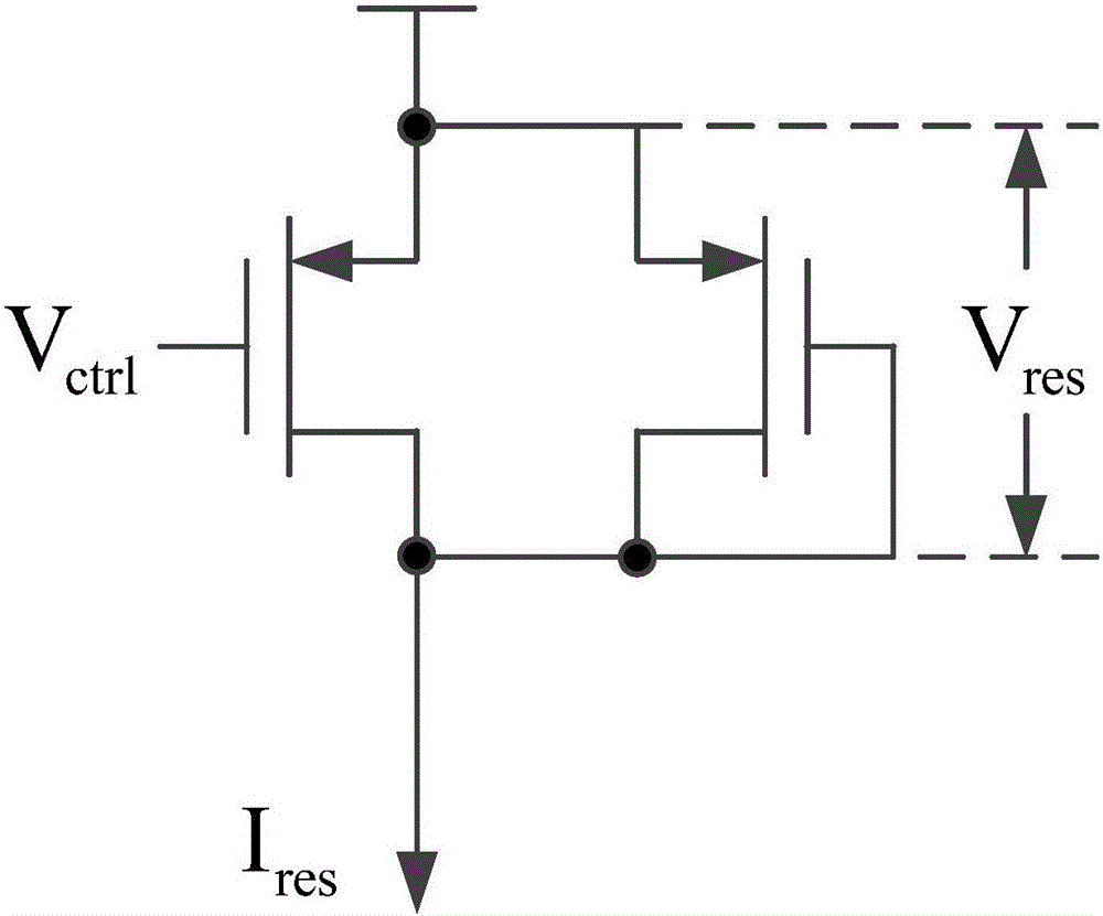
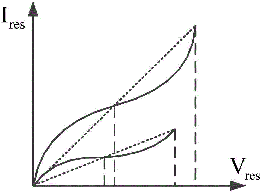

Image

  • Self-biasing circuit
  • Self-biasing circuit
  • Self-biasing circuit

Examples


Embodiment Construction

[0026] Embodiments of the present invention are described below through specific examples, and those skilled in the art can easily understand other advantages and effects of the present invention from the content disclosed in this specification. The present invention can also be implemented or applied through other different specific implementation modes, and various modifications or changes can be made to the details in this specification based on different viewpoints and applications without departing from the spirit of the present invention. It should be noted that, in the case of no conflict, the following embodiments and features in the embodiments can be combined with each other.

[0027] It should be noted that the diagrams provided in the following embodiments are only schematically illustrating the basic ideas of the present invention, and only the components related to the present invention are shown in the diagrams rather than the number, shape and shape of component...


PUM


Abstract

The invention provides a self-biasing circuit. The self-biasing circuit comprises a biasing unit suitable for generating a bias voltage and inputting the bias voltage to a differential amplifier circuit so as to keep inputting a constant current source to the differential amplifier circuit; a copying unit circuit suitable for copying a bias current source as same as that in a tail current tube in a delay unit and generating an excitation signal which is output to the differential amplifier circuit; and the differential amplifier circuit suitable for outputting an adjustable grid voltage of the tail current tube of the delay unit based on a control voltage of an annular voltage-controlled oscillator and the excitation signal in the presence of the constant current source. Through the biasing circuit, the output swing of the delay unit is ensured to change along with the change of a control voltage, so that the current-voltage characteristic of a symmetrical load in the delay unit is kept, and elimination of the one-order component of dynamic noise is facilitated. At the same time, as the bias voltage of the tail current tube in the delay unit is adjusted continuously, adoption of a common-source and common-grid structure not only can be prevented from suppressing static noise, but the influence from finite output impedance also can be counteracted.

Description

technical field [0001] The invention relates to a bias circuit, in particular to a self-bias circuit for a ring voltage-controlled oscillator. Background technique [0002] The power supply noise susceptibility of VCO includes static part and dynamic part, and the power supply includes both high-level power supply and ground power supply voltage. The power supply noise of the static part is determined by the output impedance of the current source. The larger the output impedance, the better the suppression of static power supply noise. However, high output impedance often requires a cascode structure, which is in line with the current design trend of ground power supply voltage. Contradictory. The dynamic part is determined by the load structure of the delay unit of the oscillator and the coupling capacitor at the output. The higher the linearity of the load impedance, the better the suppression of dynamic noise. But when a single MOS tube is used as the load, the adjustab...

Claims


Application Information

Patent Timeline
IPC IPC(8): H03K3/013H03K3/011
CPCH03K3/011H03K3/013
Inventor 季瑾月张瑞涛蒲杰丁一陈刚
Owner NO 24 RES INST OF CETC
Why Eureka
Try Eureka