
cabinet

A cabinet, liquid working fluid technology, applied in the direction of using liquid cooling for modification, cooling/ventilation/heating transformation, electrical components, etc. The effect of prolonging life

Active Publication Date: 2018-06-01
BEIJING BAIDU NETCOM SCI & TECH CO LTD
View PDF3 Cites 0 Cited by
  • Summary
  • Abstract
  • Description
  • Claims
  • Application Information

AI Technical Summary

Problems solved by technology

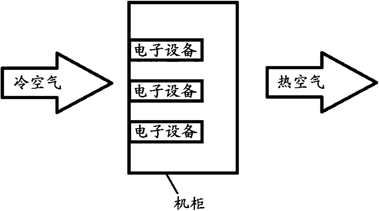
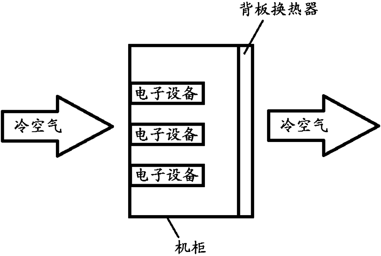
[0003] However, for the equipment heat dissipation technology of the existing data center, please refer to Figure 1a The traditional cooling scheme 1 shown in the traditional cooling scheme 1 is to use the convective circulation of air to cool the server. The difference may be that the position of the terminal air conditioner (the device that converts hot air into cold air) is different, or in the corner of the room, Either next to the cabinet, or on top of the cabinet, or at the bottom of the cabinet; refer to the Figure 1b The traditional cooling scheme 2 shown in the traditional cooling scheme 2 uses a backplane heat exchanger for backplane-level air cooling. The backplane-level air cooling has a good energy-saving effect, but there is still air circulation
Air circulation will inevitably have control problems of humidity and cleanliness (dust, harmful gases). Even today, when servers have more and more requirements for these, the above factors still restrict the life of electronic equipment, so there is a problem that the life of electronic equipment is relatively long. low problem

Method used


Image

  • cabinet
  • cabinet
  • cabinet

Examples


Embodiment Construction

[0022] The application will be further described in detail below in conjunction with the accompanying drawings and embodiments. It should be understood that the specific embodiments described here are only used to explain related inventions, rather than to limit the invention. It should also be noted that, for the convenience of description, only the parts related to the related invention are shown in the drawings.

[0023] The present application will be described in detail below with reference to the accompanying drawings and embodiments.

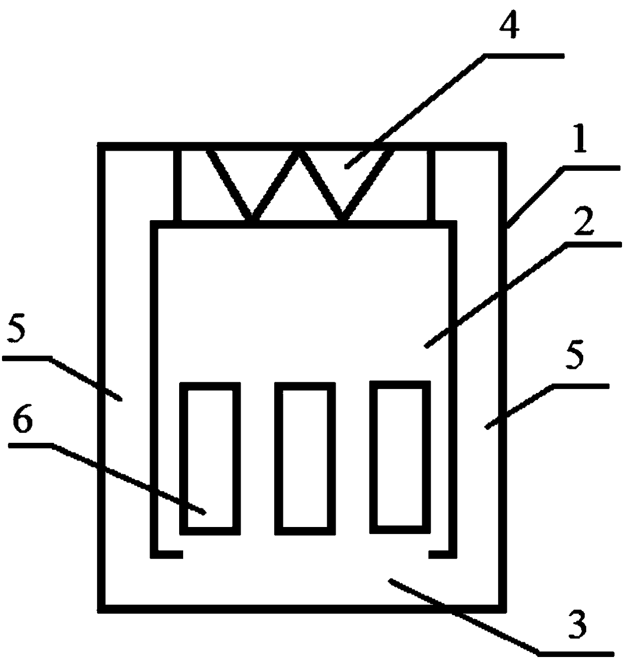
[0024] Please refer to figure 2 , which shows a schematic structural diagram of a cabinet according to the present application.

[0025] Such as figure 2 As shown, the present application discloses a cabinet, which includes: a cabinet shell 1 and a cabinet inner cavity 2 , a liquid working medium storage area 3 , a heat exchanger 4 , and a transmission channel 5 arranged in the cabinet shell 1 .

[0026] Here, the above-mentioned ca...


PUM


Abstract

This application discloses the cabinet. A specific embodiment of the method comprises: a cabinet housing and a cabinet cavity disposed within the cabinet housing, a liquid working fluid placement area, a heat exchanger, a transmission channel, wherein: the cabinet cavity is set to a vacuum state and for placing the electronic device to be cooled; The liquid working fluid placement area is used to place the liquid working medium, wherein the liquid working medium is converted into a gaseous working medium into the heat exchanger after cooling the electronic device to be cooled; The heat exchanger is used to liquefy the gaseous working medium as a liquid working medium and introduce the liquid working medium from the liquefaction of the gaseous working medium into the transmission channel; The transmission channel connects the heat exchanger and the liquid working fluid placement area, and is used to introduce the liquid working medium from the liquefaction of the gaseous working medium into the liquid working fluid placement area. This embodiment eliminates the impact of humidity, cleanliness, etc. brought by air circulation on the electronic equipment, thereby extending the life of the electronic equipment.

Description

technical field [0001] The present application relates to the technical field of hardware equipment, in particular to the technical field of heat dissipation hardware, and in particular to cabinets. Background technique [0002] With the deepening of informatization and the development of various industries, such as the development of the mobile Internet industry and the Internet of Things industry, more and more devices are connected to the network. The resulting large increase in data transmission has brought about a large increase in the development of networks and the construction of data centers. Therefore, more and more electronic devices, such as servers, routers, and switches, are required to process data. [0003] However, for the existing data center equipment heat dissipation technology, please refer to Figure 1a The traditional cooling scheme 1 shown in the traditional cooling scheme 1 is to use the convective circulation of air to cool the server. The differenc...

Claims


Application Information

Patent Timeline
Patent Type & Authority Patents(China)
IPC IPC(8): H05K7/20
CPCH05K7/2029H05K7/20818H01L23/427H05K7/20336H05K7/208
Inventor 唐虎谭显光周天宇丁瑞权张炳华
Owner BEIJING BAIDU NETCOM SCI & TECH CO LTD
Learn More