Worm and gear drive mechanism and worm and gear speed reducer

A technology of worm gear and transmission structure, which is applied to transmission parts, mechanical equipment, belts/chains/gears, etc. It can solve problems such as poor transmission, changes in transmission speed ratio, and decreased meshing accuracy of worm gear transmission, and achieves the elimination of fixed-point meshing Poor state, guarantee the tightness of cooperation, and the effect of filling the gap in the industry

Inactive Publication Date: 2016-10-19
王卓
View PDF5 Cites 3 Cited by
  • Summary
  • Abstract
  • Description
  • Claims
  • Application Information

AI Technical Summary

Problems solved by technology

After the worm gear and worm transmission structure in the prior art is used for a certain period, due to tooth wear, the meshing between the teeth will be poor, the noise will increase, and the transmission speed ratio will also change. In this case, the entire worm will eventually be scrapped or the overall transmission is discarded
From another feature of worm gear transmission, the traditional worm gear transmission structure bears a large axial force during operation. Therefore, for a worm gear that is loaded in one direction for a long time, the single-sided tooth profile wears seriously. , and because the overall worm is inconvenient to adjust the axial position, usually the only way to solve tooth wear is to replace the new worm
In addition, the worm gear and worm gear transmission structure in the prior art and the reducer using this transmission structure must ensure that the worm is always in a horizontal state in actual use, otherwise the transmission meshing accuracy of the worm gear and worm will be reduced, resulting in poor transmission

Method used


Image

  • Worm and gear drive mechanism and worm and gear speed reducer
  • Worm and gear drive mechanism and worm and gear speed reducer
  • Worm and gear drive mechanism and worm and gear speed reducer

Examples


Embodiment Construction

[0019] The present invention will be described in detail below with reference to the drawings and examples.

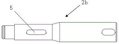
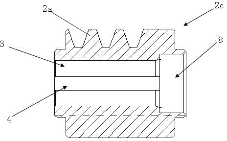
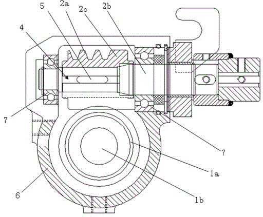
[0020] figure 1 It is a schematic diagram of the worm shaft in the worm gear transmission structure of the present invention; figure 2 It is a schematic diagram of the gear rod in the worm gear transmission structure of the present invention; image 3 It is a schematic diagram of the worm gear reducer adopting the worm gear transmission structure of the present invention.

[0021] Such as Figure 1 to Figure 3 As shown, the worm gear transmission structure of the present invention includes a worm wheel 1 and a worm screw 2, wherein the worm wheel includes a toothed disc 1a and a worm shaft 1b coaxially arranged, the worm wheel shaft and the toothed disc are coaxially arranged and rotate synchronously, and the worm includes a helical tooth 2a And the worm shaft 2b, the toothed disc and the worm are vertically arranged, the toothed disc and the helical teeth mesh wit...


PUM


Abstract

A worm gear transmission structure and a worm gear reducer, including a worm gear and a worm, wherein the worm gear includes a toothed plate and a worm shaft arranged coaxially, the worm includes helical teeth and a worm shaft, the toothed plate and the helical teeth mesh with each other, and the worm includes a barrel Shaped gear bar, the helical teeth are arranged on the outer periphery of the gear bar, and the worm shaft runs through the gear bar and is arranged coaxially with the gear bar; the radial position between the gear bar and the worm shaft is fixed, and at the same time, the gear bar slides and translates along the axial direction of the worm shaft. The worm shaft can be used for a long time because it is a non-wearing part, and the gear rod as a wearing part can be replaced at any time according to the usage situation, and the standardization and serialization of products can also be realized according to requirements. Since the toothed rod can slide and translate freely on the worm shaft, it can eliminate the poor meshing state of the fixed point caused by the error of the tooth profile. In addition, the present invention can be applied to the installation and use environment where the worm is in a non-horizontal state, which fills the gap in the industry.

Description

technical field [0001] The invention relates to the technical field of mechanical transmission, in particular to a low-cost worm gear transmission structure and a worm gear reducer with longer service life. Background technique [0002] The worm gear transmission structure is a power transmission mechanism, which is often used in speed reduction models. By using the speed converter generated by gear meshing, the rotation speed of the motor (motor) is reduced to the desired rotation speed, and a large torque mechanism is obtained. . [0003] In the mechanism currently used to transmit power and motion, the application range of the reducer is quite wide. In structural design and manufacture, usually the helical teeth on the periphery of the worm and the transmission shaft are integrated. Therefore, the tooth shape and the transmission shaft connected together must have a more precise coaxiality requirement, and at the same time, the worm shaft support also has a precise coax...

Claims


Application Information

Patent Timeline
Patent Type & Authority Applications(China)
IPC IPC(8): F16H55/24F16H55/06F16H57/023
Inventor 王卓
Owner 王卓
Why Eureka
Try Eureka