Supercharge Your Innovation With Domain-Expert AI Agents!

Moving object detection method of mobile camera under high parallax

A technology of moving targets and moving cameras, applied in image analysis, instruments, calculations, etc., can solve problems such as extremely high hardware requirements, poor robustness, and inapplicability

Active Publication Date: 2016-10-19
无锡南理工新能源电动车科技发展有限公司
View PDF2 Cites 13 Cited by
  • Summary
  • Abstract
  • Description
  • Claims
  • Application Information

AI Technical Summary

Problems solved by technology

Among them, the homography matrix uses the mapping relationship between matching point pairs on the same plane, which is especially suitable for situations where the scene parallax can almost be ignored for drone aerial photography; the basic matrix uses the emitter geometric relationship between image matching point pairs to detect moving objects ; The multi-viewpoint image used by the trifocal tensor is increased from two views to three views, and the mathematical quantity representing the intrinsic projective geometric relationship between images that does not depend on the scene structure is also changed from the basic matrix to the trifocal tensor, but the calculation more complicated
[0004] However, the above traditional methods require a reference calibration object with known geometric information, and the calibration method based on active vision needs to use accurate pan / tilt and other hardware platforms to provide the orientation information of the camera at any time, which has extremely high hardware requirements and is not suitable for portable cameras; Self-calibration methods such as basic matrix and three-view tensor, although not demanding on calibration scenes and calibration instruments, often have a large workload, poor robustness, and low accuracy

Method used


Image

  • Moving object detection method of mobile camera under high parallax
  • Moving object detection method of mobile camera under high parallax
  • Moving object detection method of mobile camera under high parallax

Examples


Embodiment Construction

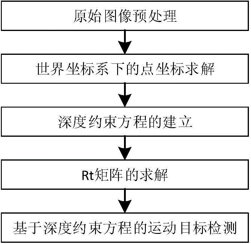
[0025] combine figure 1 , the mobile camera moving object detection method under the strong parallax of the present invention, comprises the following specific steps:

[0026] Step 1: Original image preprocessing: First, match the pixels of the two frames before and after. The mature KLT tracking algorithm has the advantages of fast speed, high precision, and strong anti-noise ability, so the KLT tracking algorithm is used to compare the two frames before and after. The image pixels are matched to obtain the image coordinates of the matching points of the two frames of images (u 1 ,v 1 ), (u 2 ,v 2 ), where u 1 , v 1 Respectively represent the abscissa and ordinate of the pixel on the previous frame image, u 2 , v 2 Respectively represent the abscissa and ordinate of the pixel on the next frame image; secondly, use depth detectors such as Kinect camera and laser radar to obtain the depth information Z of the matching points of the two frames of images relative to the ca...


PUM


Abstract

The invention proposes a moving camera moving target detection method under strong parallax. Use the rotation matrix R and the translation matrix t to describe the camera motion between two frames, and obtain the relationship between the points on the second frame image and the world coordinate system, so as to obtain the depth constraint equation; the coordinates of all matching points on the second frame image and The corresponding depth information is brought into the depth constraint equation to obtain the optimal solution of the Rt matrix of the depth constraint equation; the image point coordinates calculated by the depth constraint equation are multiplied by the corresponding depth information; The results are respectively used as two three-dimensional coordinate points, the distance between the two three-dimensional coordinate points is calculated, and the distance is normalized. If the normalized distance is greater than the set threshold, it is judged that the point corresponding to the distance is a moving target. Otherwise, the point corresponding to this distance is the background. The invention can solve the problem of parallax in three-dimensional scenes under mobile platforms such as vehicle-mounted handhelds, and can detect moving objects in real time and efficiently.

Description

technical field [0001] The invention belongs to the field of digital image processing and pattern recognition, in particular to the field of target recognition and tracking based on image processing, and specifically relates to a moving target detection method of a mobile camera under strong parallax. Background technique [0002] Automatic moving target detection technology is the key technology in the target search and tracking system, which provides preliminary information for subsequent track association, target recognition, tracking and other technologies. In the traditional moving object detection system, the camera is usually stationary, and it is widely used in video surveillance, traffic detection and other systems. However, in mobile platforms such as vehicles and handhelds, due to the movement of the camera, the 3D scene will produce parallax. At this time, it is necessary to effectively estimate the scene parallax. [0003] Traditional methods generally use the ...

Claims


Application Information

Patent Timeline
IPC IPC(8): G06T7/20
Inventor 顾国华丁祺孔筱芳徐富元
Owner 无锡南理工新能源电动车科技发展有限公司
Features
  • R&D
  • Intellectual Property
  • Life Sciences
  • Materials
  • Tech Scout
  • Unparalleled Data Quality
  • Higher Quality Content
  • 60% Fewer Hallucinations
Learn More