Mixing stirrer with double feed inlets

A mixing and double-feeding technology, which is applied to mixers with rotating containers, mixers, mixer accessories, etc., can solve the problems of high labor intensity, waste of manpower, material and financial resources, and low production efficiency, and achieve improved mixing and mixing. Effect of Efficiency and Mixing Quality on Mixing

Inactive Publication Date: 2016-10-26
HARBIN HUAZAO BIOTECH DEV
View PDF6 Cites 18 Cited by
  • Summary
  • Abstract
  • Description
  • Claims
  • Application Information

AI Technical Summary

Problems solved by technology

[0002] At present, equipment mechanization and automation have been applied in the fields of food, feed, and medicine in my country, but mechanized control has not been realized in some key processes, such as stirring and mixing of materials, and the traditional Chinese manual operation method is still followed. High labor intensity and low production efficiency
[0003] The existing mixing and stirring devices generally only have one feeding port. When people need to mix and stir two different materials, they need to put the two materials in one container in advance or mix the different materials twice. It is put into the...

Method used


Image

  • Mixing stirrer with double feed inlets

Examples


Embodiment 1

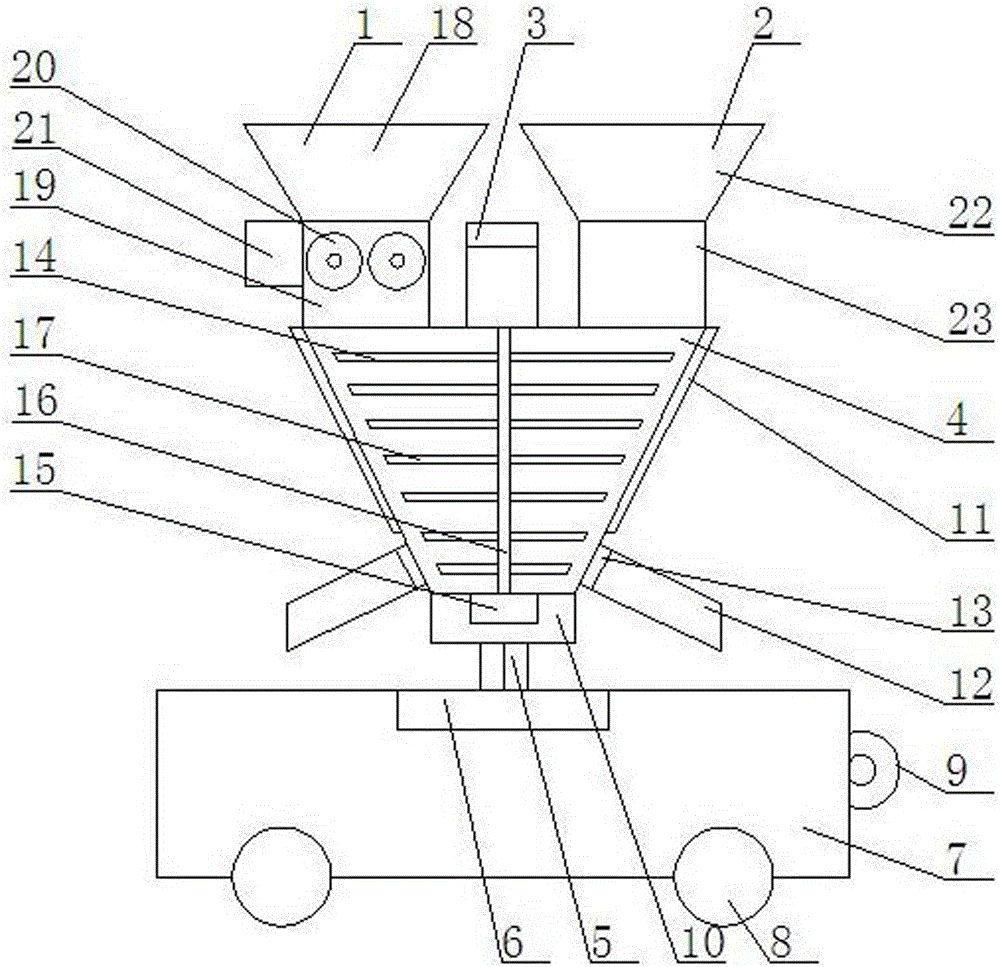
[0018] Such as figure 1 As shown, a mixing and agitating device with double feeding ports includes a left feeding port 1, a right feeding port 2, a control box 3, a rotating mixing drum 4, a rotating shaft 5, a rotating motor 6, a frame 7, Walking wheel 8, traction hook 9, described left feeding inlet 1 is installed on the left side of the top of rotating mixing drum 4, and described right feeding inlet 2 is installed on the right side of rotating mixing drum 4 top, and described control box 3 devices are rotating In the middle of the top of the mixing cylinder 4, the bottom end of the rotating mixing cylinder 4 is installed on the rotating fixed box 10, and the rotating fixed box 10 is connected to the bottom rotating motor 6 through the rotating shaft 5, and the rotating motor 6 is installed on the frame 7 , the bottom end of the frame 7 is equipped with road wheels 8, and the right side of the frame 7 is equipped with a traction hook 9.

Embodiment 2

[0020] The rotating mixing drum 4 is an inverted conical rotating mixing drum 4 without a conical head, and the rotating and fixing box 10 at the bottom of the rotating mixing drum 4 is a cylindrical rotating and fixing box 10 .

Embodiment 3

[0022] An electric heating device 11 is installed on the inverted conical surface of the rotating mixing cylinder 4, and two left and right discharge pipes 12 are installed on the lower end of the inverted conical surface of the rotating mixing cylinder 4, and an electric control valve is installed on the discharging pipe 12. 13.


PUM


Abstract

The invention relates to a mixing stirrer with double feed inlets. The mixing stirrer comprises a left feed inlet, a right feed inlet, a control tank, a rotating mixing cylinder, a rotating shaft, a rotating motor, a rack, traveling wheels and a draw hook, wherein, the left feed inlet is arranged at the left side of the top end of the rotating mixing cylinder, the right feed inlet is arranged at the right side of the top end of the rotating mixing cylinder, the control tank is arranged in the middle of the top end of the rotating mixing cylinder, the bottom end of the rotating mixing cylinder is arranged on a rotating fixed tank which is connected with a rotating motor at the bottom end through the rotating shaft, the rotating motor is arranged on the rack, the traveling wheels are arranged at the bottom end of the rack, and the draw hook is arranged on the right side surface of the rack. The mixing stirrer is provided with double feed inlets, so that two different materials can be fed into the mixing stirrer simultaneously, and the mixing and stirring efficiency and mixing and stirring quality can be beneficially improved; and a crushing device is arranged inside one of the feed inlets, so that materials required for crushing can be crushed.

Description

technical field [0001] The invention relates to a mixing and stirring device, in particular to a mixing and stirring device with double feeding ports. Background technique [0002] At present, equipment mechanization and automation have been applied in the fields of food, feed, and medicine in my country, but mechanized control has not been realized in some key processes, such as stirring and mixing of materials, and the traditional Chinese manual operation method is still followed. The labor intensity is high and the production efficiency is low. [0003] The existing mixing and stirring devices generally only have one feeding port. When people need to mix and stir two different materials, they need to put the two materials in one container in advance or mix the different materials twice. It is put into the mixing and stirring device from a feed port, which leads to high difficulty in mixing and stirring, and uneven mixing and stirring are prone to occur, and some materials...

Claims


Application Information

Patent Timeline
IPC IPC(8): B01F9/12B01F15/02B01F15/06B02C4/08B01F29/83
CPCB02C4/08B01F29/40113B01F29/4032B01F29/83B01F35/71B01F2035/99B01F35/92
Inventor 孙漫泽
Owner HARBIN HUAZAO BIOTECH DEV
Why Eureka
Try Eureka