Reaction kettle

A technology of a reaction kettle and a stirring device, which is applied in the field of reaction kettles, can solve the problems of unclean cleaning, influence on liquid reaction, low efficiency, etc., and achieve the effects of convenient and effective cleaning, uniform liquid temperature and high work efficiency

Active Publication Date: 2016-10-26
郯城众一科环化工有限公司
View PDF5 Cites 4 Cited by
  • Summary
  • Abstract
  • Description
  • Claims
  • Application Information

AI Technical Summary

Problems solved by technology

[0002] The chemical liquid reaction kettle generally includes a kettle body and a stirring system. The top of the kettle body is provided with a feeding port, and the bottom of the kettle body is provided with a discharge port. The device includes a stirring shaft and a stirring blade, the stirring shaft is connected to the motor, and the stirring blade is fixedly connected to the stirring shaft; impurities in the raw materials such as some solid chemical particles will also participate in the reaction, which not only wastes raw materials, but also generates other products, which is different from the plan. The product does not match, or the impurities in the raw materials do not participate in the reaction, but the product after the reaction is doped with impurities, which greatly affects the quality of the product. In addition, after using the reactor for many times, a certain amount of The chemical crystallization of the traditional reactor can only be cleaned through some holes such as the feed port on the wall of the kettle, and it is inconvenient to clean, and the cleaning is not clean. In addition, when the agitator stirs the liquid in the kettle body, it will produce clockwise Or counterclockwise vortex, the liquid in the kettle body is mixed along the vortex, but the mixing method is inefficient, and when the various liquid reactions in the kettle body need a certain temperature, along the Vortex rotation for mixing will also make the temperature of the liquid in each area uneven, affecting the reaction of the liquid

Method used


Image

  • Reaction kettle
  • Reaction kettle
  • Reaction kettle

Examples


Embodiment 1

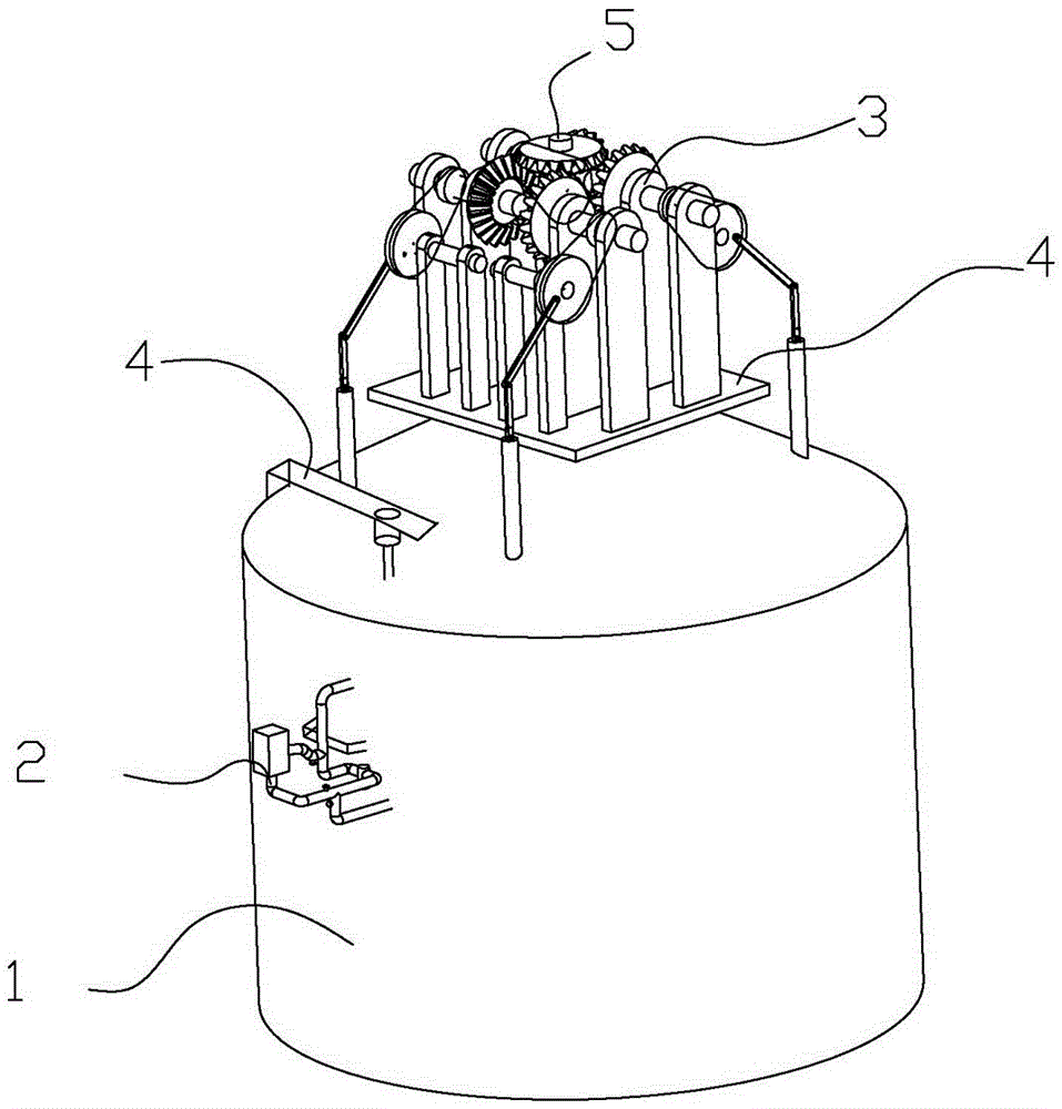
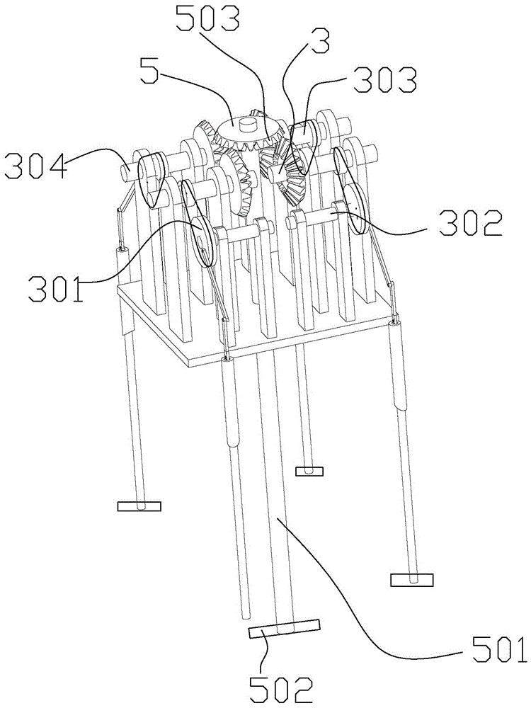
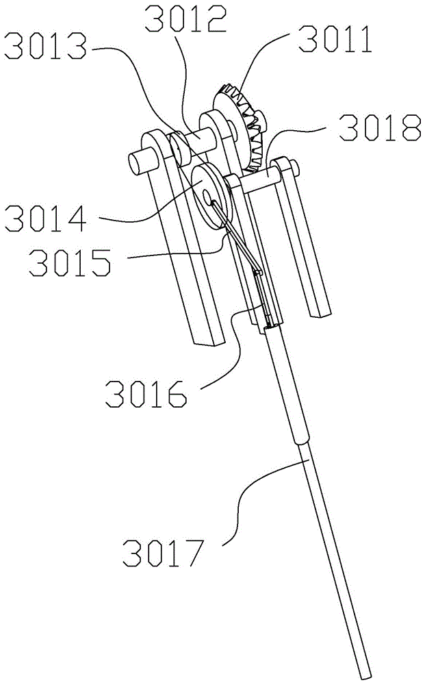
[0050] Example 1: as figure 1 , figure 2 , image 3 , Figure 4 , Figure 5 , Image 6 , Figure 7 , Figure 8 , Figure 9 , Figure 10 , Figure 11 , Figure 12 , Figure 13 , Figure 14 , Figure 15 , Figure 16 , Figure 17 , Figure 18 As shown in the figure, a reaction kettle comprises a reaction kettle body 1, a negative pressure circulating filter device 2 arranged on the reaction kettle body 1 for filtering liquid raw materials, a rotating device for stirring the liquid in the reaction kettle body 1 The lifting stirring device 3 and the main stirring device 5 and the mounting frame 4 required for installing the rotating lifting stirring device 3 and the main stirring device 5 .

[0051] The reaction kettle body 1 includes an upper reaction kettle body 1a, a lower reaction kettle body 2a connected to the upper reaction kettle body 1a, a first sealing ring 3a and a second sealing ring 4a for sealing, and a lower reaction kettle body 2a. The upper part i...


PUM


Abstract

The invention discloses a detachable filtering reaction kettle. The reaction kettle comprises a reaction kettle body, wherein the reaction kettle body comprises an upper reaction kettle body, a lower reaction kettle body connected with the upper reaction kettle body, a first sealing ring and a second sealing ring for sealing, and a negative pressure circulating filter apparatus arranged on the reaction kettle body and used for filtering a raw material, wherein the negative pressure circulating filter apparatus comprises a first filter apparatus connected with a motor and a second filter apparatus connected with the first filter apparatus. The reaction kettle is provided with the filter apparatus and divided into two; the reaction kettle is provided with the filter apparatus, so that impurities in the raw material are filtered prior to the chemical reaction of the raw material, simplicity and convenience are realized, and a reaction product is purer; and the reaction kettle is divided into two, so that chemical crystals remaining on the wall of the reaction kettle after multiple times of reaction can be conveniently cleaned, and the cleaning is facilitated.

Description

technical field [0001] The invention relates to the technical field of chemical equipment, in particular to a reaction kettle. Background technique [0002] The chemical liquid reaction kettle generally includes a kettle body and a stirring system. The top of the kettle body is provided with a feeding port, and the bottom of the kettle body is provided with a discharging port. The stirring system includes a motor arranged on the top of the kettle body and a stirrer arranged in the kettle body. The mixer includes a stirring shaft and a stirring blade, the stirring shaft is connected with the motor, and the stirring blade is fixedly connected with the stirring shaft; impurities in the raw materials such as some solid chemical particles will also participate in the reaction, which not only wastes the raw materials, but also generates other products. The product does not conform to the original product, or the impurities in the raw material do not participate in the reaction, bu...

Claims


Application Information

Patent Timeline
Patent Type & Authority Applications(China)
IPC IPC(8): B01J19/18B01J19/00
CPCB01J19/0066B01J19/0073B01J19/18
Inventor 李德清
Owner 郯城众一科环化工有限公司
Why Eureka
Try Eureka