
Plate clamp special for power transformation operation and maintenance

A technology of operation and maintenance and board clamping, which is applied to folders, writing pads, printing, etc., can solve the problems of inconvenient writing, no function, and inconvenient operation, and achieve the effects of improving work efficiency, convenient carrying, and convenient operation

Inactive Publication Date: 2016-10-26
YANCHENG POWER SUPPLY CO STATE GRID JIANGSU ELECTRIC POWER CO +4
View PDF8 Cites 5 Cited by
  • Summary
  • Abstract
  • Description
  • Claims
  • Application Information

AI Technical Summary

Problems solved by technology

Traditional clips often only have a metal iron clip to clamp the center of the paper, and there are no fixed parts around the paper, so the paper often bulges, wrinkles, and shifts, causing a lot of inconvenience to writing, and when the paper is changed, It is often inconvenient to operate by re-clamping after reversing the order of the paper. Finally, if there is an emergency in engineering maintenance, it is necessary to quickly record the instrument parameters, and there is no corresponding function to realize it.
Therefore, how to create a new type of special board clip for power substation operation and maintenance, which can not only be applied to the processing and writing of multiple pages of paper, but also be able to turn the pages of the paper while keeping the upper and lower order of the paper unchanged, and Solve the problem that the paper after turning the page is not suitable to be held by hand

Method used


Image

  • Plate clamp special for power transformation operation and maintenance
  • Plate clamp special for power transformation operation and maintenance
  • Plate clamp special for power transformation operation and maintenance

Examples


Embodiment Construction

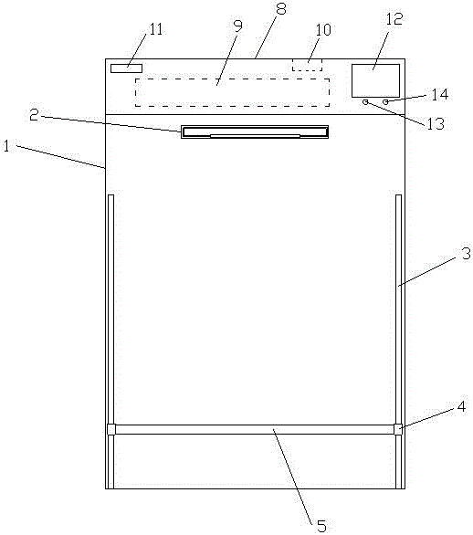
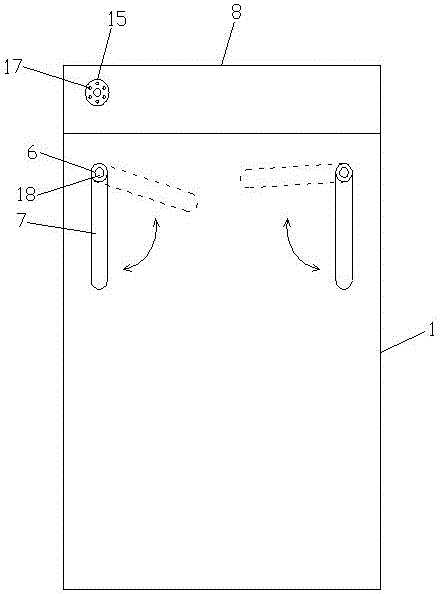
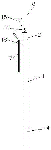
[0015] Such as Figure 1-3 The special plate clamp for power transformation operation and maintenance shown includes a bottom plate 1, a clamping portion 2 is provided on the front upper end of the bottom plate 1, and chute 3 is longitudinally provided on the left and right sides of the front of the bottom plate 1, and the slide The groove 3 is provided with sliders 4, and the sliders 4 are connected by bar-shaped barriers 5. The left and right sides of the reverse side of the bottom plate 1 are provided with a turntable 6, and the turntable 6 is provided with a clamping bar 7. The top of the bottom plate 1 is provided with a control device 8, the interior of the control device 8 is provided with a storage battery 9 and a memory card 10, a time display screen 11 is provided at the upper left corner of the front, and a liquid crystal display screen 12 is provided at the upper right corner. The bottom of the screen 12 is provided with a power switch 13 and a camera switch 14, an...


PUM


Abstract

The invention relates to a plate clamp special for power transformation operation and maintenance. The plate clamp comprises a bottom plate. A clamping part is arranged at the upper end of the front face of the bottom plate. Sliding grooves are formed in the left side and the right side of the front face of the bottom plate in the longitudinal direction. Sliding blocks are arranged on the sliding grooves and are connected through a bar-shaped blocking part. Rotary discs are arranged on the left side and the right side of the back face of the bottom plate and are provided with clamping bars. A control device is arranged on the top of the bottom plate. A storage battery and a storage card are arranged in the control device. A time display screen is arranged at the upper left corner of the front face of the control device, and a liquid crystal display screen is arranged at the upper right corner of the front face of the control device. A power switch and a camera shooting switch are arranged below the liquid crystal display screen. A camera shooting device is arranged on the back face of the control device. The camera shooting device is arranged on the back face of the liquid crystal display screen. The plate clamp is convenient to carry and convenient and quick to operate and can be suitable for treatment and writing of multiple pieces of paper, page turning can also be conducted on the paper under the condition that the vertical sequence of the paper is kept unchanged, and the problem that the paper obtained after page turning is not suitable for being held by hands is solved.

Description

technical field [0001] The invention relates to the technical field of electric power engineering, in particular to a special plate clamp for power transformation operation and maintenance. Background technique [0002] In the field of electric power, it is necessary to record the time frequently during the switching operation, and the plate clips currently used are not capable of the function of time recording. For electric power engineering technicians, it is often necessary to detect and record the parameter changes and operating conditions of various instruments in real time. Generally, in order to facilitate movement and writing, electric power engineering technicians will use board clips to hold recording paper for mobile office. Traditional clips often only have a metal iron clip to clamp the center of the paper, and there are no fixed parts around the paper, so the paper often bulges, wrinkles, and shifts, causing a lot of inconvenience to writing, and when the paper...

Claims


Application Information

Patent Timeline
Patent Type & Authority Applications(China)
IPC IPC(8): B42F9/00B43L3/00
CPCB42F9/001
Inventor 张旭松江素红雷斌张卫东沈泉肖红谊
Owner YANCHENG POWER SUPPLY CO STATE GRID JIANGSU ELECTRIC POWER CO
Learn More