A device for mutual charging of electric vehicles

A technology for electric vehicles and mutual charging, which is applied in the direction of electric vehicle charging technology, electric vehicles, battery circuit devices, etc., can solve problems such as immobility, long search time, and uneven distribution of charging piles, so as to improve emergency response capabilities and prolong The effect of battery life and ease of pricing operation

Active Publication Date: 2018-07-03
WUHAN UNIV
View PDF5 Cites 0 Cited by
  • Summary
  • Abstract
  • Description
  • Claims
  • Application Information

AI Technical Summary

Problems solved by technology

[0003] Traditional charging methods are generally divided into two types: one is to build a large number of charging piles to provide power for cars. As of 2015, there are more than 11,000 charging piles that have been built or are under construction in Wuhan alone. The distribution is uneven, the search time is too long, and the charging is slow. The other is to install a charger under the road to charge the driving car. Although the problem of long search time is solved, the construction cost is relatively high. There are only a few cities in China such as Guangzhou for pilot projects
Therefore, there will be an embarrassing situation in which the battery power of the electric vehicle user is insufficient or even exhausted on the road and cannot move, which brings great inconvenience to the user of the electric vehicle, and also limits the promotion of the electric vehicle to a certain extent.

Method used


Image

  • A device for mutual charging of electric vehicles
  • A device for mutual charging of electric vehicles
  • A device for mutual charging of electric vehicles

Examples


Embodiment Construction

[0034] Embodiments of the present invention will be described in detail below in conjunction with the accompanying drawings.

[0035] The following disclosure provides many different embodiments or examples for implementing different structures of the present invention. In order to simplify the disclosure of the present invention, the components and arrangements of specific examples are described below, which are for illustration only and are not intended to limit the present invention. Furthermore, the present invention may repeat reference numerals and / or letters in different instances. This repetition is for the purpose of simplicity and clarity and does not in itself indicate a relationship between the various embodiments and / or arrangements discussed. In addition, various specific process and material examples are provided herein, but one of ordinary skill in the art may recognize the applicability of other processes and / or the use of other materials. Additionally, conf...


PUM


Abstract

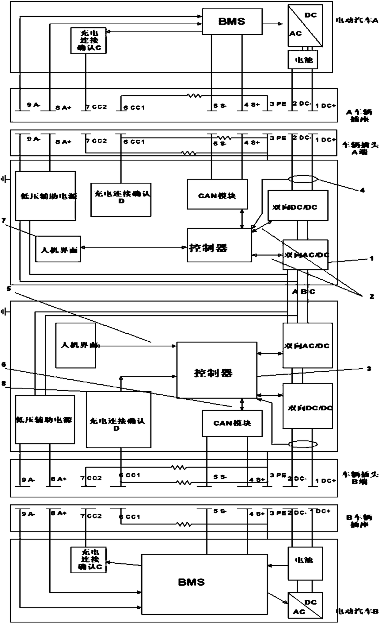
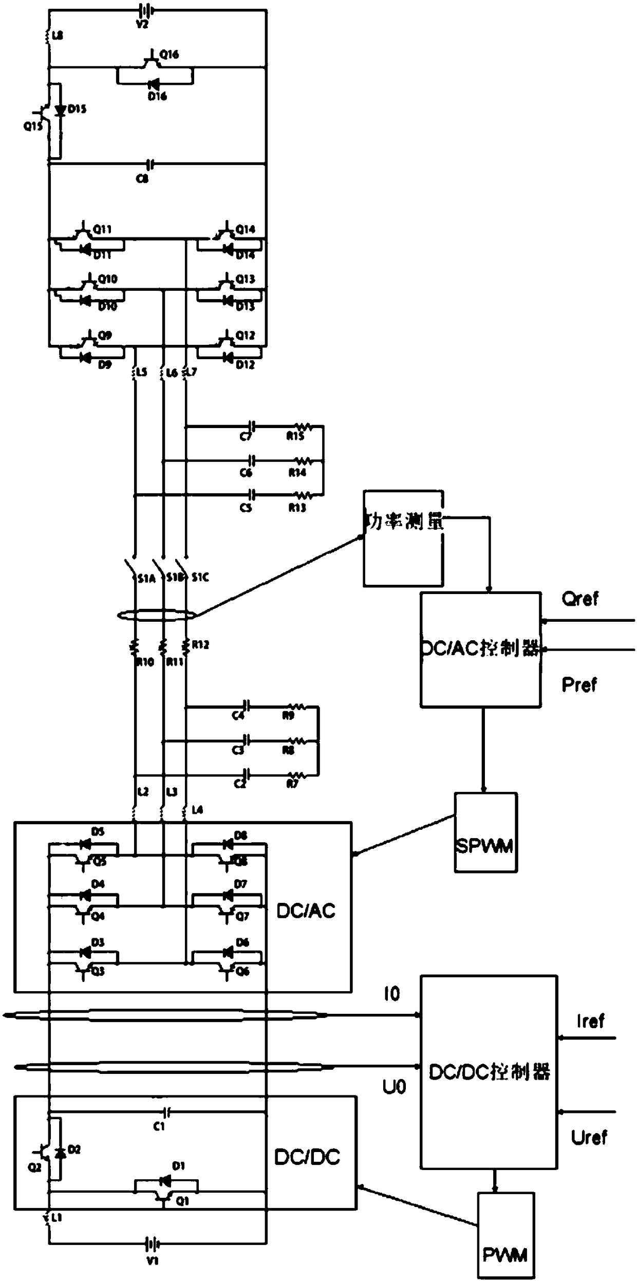
The invention relates to the technical field of electric automobile charging, in particular to an electric automobile inter-charging device. The electric automobile inter-charging device comprises an electric automobile A and an electric automobile B, and the electric automobile A and the electric automobile B each comprise a battery connected with a BMS and a charging connection determination C; the electric automobile inter-charging device further comprises a charging conversion device A, a charging conversion device B and a charging connecting device. The charging conversion device A and the charging conversion device B each comprise a charging-discharging main circuit, a signal sampling module, a controller, an IGBT driving module, a CAN module, a charging connection determination D, a human-computer interface, a low-voltage auxiliary power source and a power source module; the charging connecting device comprises a vehicle socket A, a vehicle socket B, a vehicle plug A and a vehicle plug B, wherein the vehicle socket A and the vehicle socket B are arranged on the electric automobile A and the electric automobile B respectively, and the vehicle plug A and the vehicle plug B are arranged on the charging conversion device A and the charging conversion device B respectively. According to the device, each driving vehicle serves as a movable power source, a vehicle-vehicle power supplying device is achieved in a direct-current-alternating-current-power-source-conversion mode, and electric automobiles can be rapidly and conveniently charged in the driving process.

Description

technical field [0001] The invention belongs to the technical field of electric vehicle charging, and in particular relates to a device for mutual charging of electric vehicles. Background technique [0002] With the depletion of petrochemical resources and the intensification of global air pollution, the number of automobiles is increasing day by day, which poses severe challenges to traditional internal combustion engine vehicles. Especially in China, where the economy is developing at a high speed, oil consumption and imports continue to rise, which has created unprecedented pressure on the development of the automobile industry, which consumes a lot of fuel. With the development of the times, electric vehicles are more and more likely to replace traditional cars. As a new generation of transportation, electric vehicles have incomparable advantages in terms of energy saving, emission reduction and pollution reduction. However, with the rapid increase in the number of el...

Claims


Application Information

Patent Timeline
Patent Type & Authority Patents(China)
IPC IPC(8): B60L11/18H02J7/02H02J7/00
CPCB60L53/14H02J7/0021H02J7/022Y02T10/70Y02T10/7072Y02T90/14
Inventor 崔晓晖古思丽李伟
Owner WUHAN UNIV
Why Eureka
Try Eureka