Combined building block and construction method for forming wall body with combined building block

A construction method and block technology, which can be applied in the treatment of walls, building materials, building components, etc., can solve the problems of inability to popularize and popularize reinforced blocks, poor integrity of village buildings, and low seismic fortification level, and achieve stiffness degradation performance. Good, good mechanical properties, strong resistance to external forces

Inactive Publication Date: 2016-10-26
XI'AN UNIVERSITY OF ARCHITECTURE AND TECHNOLOGY
7 Cites 2 Cited by

AI-Extracted Technical Summary

Problems solved by technology

[0004] Aiming at the problems existing in the prior art, the object of the present invention is to provide a construction method of combining blocks and forming walls by using combined blocks, which solves the problems of low level...

Method used

(4) add ring beam, construction column in masonry wall piece, the stress of body of wall is even, although body of wall thickness is thinner, but with respect to brickwork wall piece, its ultimate bearing capacity is more High, stronger resistance to external force, and greater rigidity.
In the above-mentioned construction method of utilizing combined blocks to form various body of walls, transverse reinforcing bars are arranged in strip grooves, compared with placing transverse reinforcing bars in mortar joints in the prior art, the viscosity of mortar can be improved. knot performance.
The strip groove 3 that is set on the described wall block 4 and the strip groove 3 that is set on the whole brick cleaning block 1 are all used for laying transverse reinforcement; Traditional adjacent two vertically Horizontal reinforcing bars are arrang...

Abstract

The invention discloses a combined building block and a construction method for forming a wall body with the combined building block. The reinforced block masonry disclosed by the invention is of a structure which is high in earthquake fortification level, small in construction difficulty, good in overall property, excellent in structural property and low in manufacturing cost, is capable of relatively well solving the problems of buildings in villages and towns, has good characteristics of an assembled structure, and has relatively good application and popularization prospects.

Application Domain

WallsBuilding material handling

Technology Topic

Structural propertyFortification +1

Image

  • Combined building block and construction method for forming wall body with combined building block
  • Combined building block and construction method for forming wall body with combined building block
  • Combined building block and construction method for forming wall body with combined building block

Examples

  • Experimental program(1)

Example Embodiment

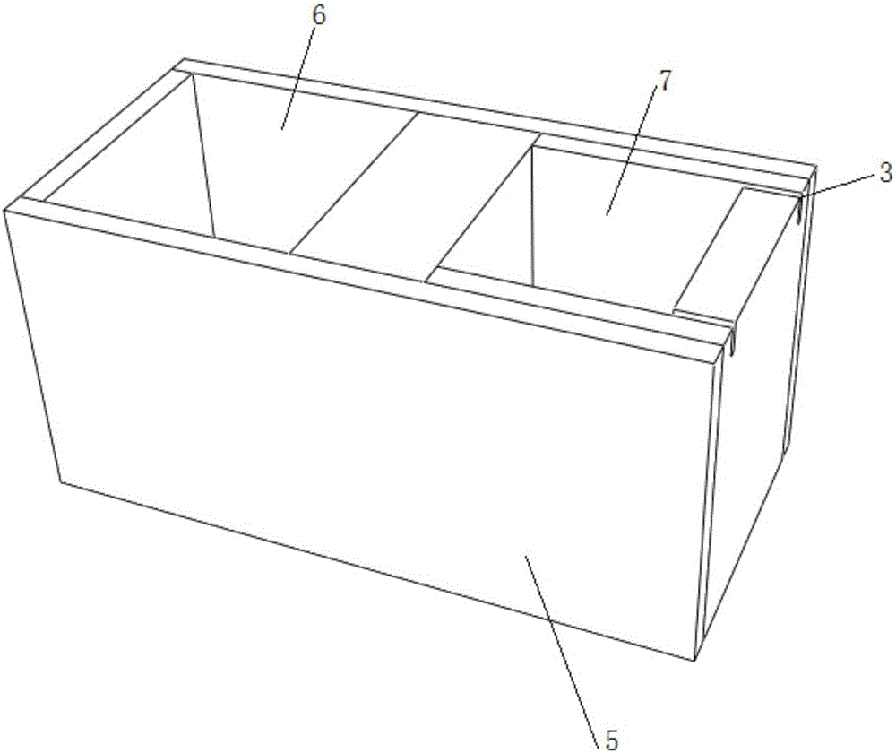
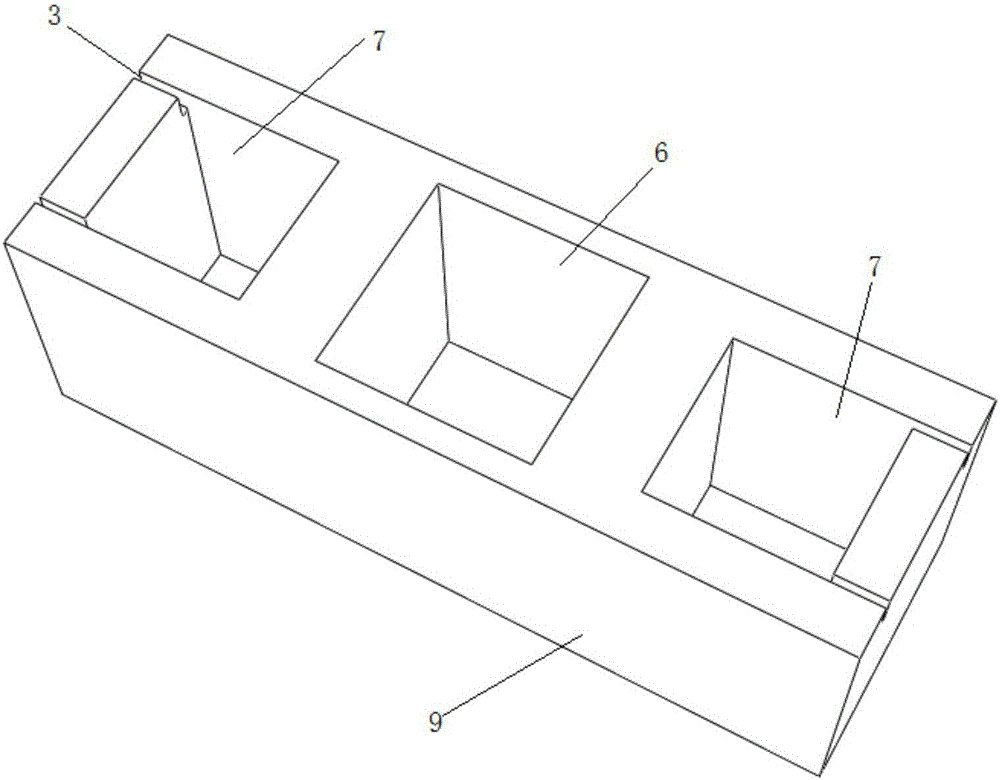
[0072] Aiming at the problems existing in the construction of villages and towns, the present invention proposes a combined block, which has advantages in overall performance, construction difficulty, and cost compared with the existing reinforced block. The main idea of ​​using combined blocks for masonry construction: except for the foundation, all the above-ground parts adopt prefabricated construction technology, and no formwork is required.
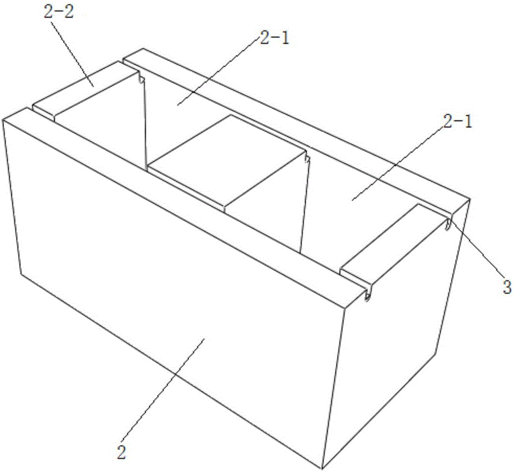
[0073] Following the above technical scheme, the combined block of the present invention includes a full-brick cleaning block 1 and a wall block 2. The full-brick cleaning block 1 is provided with multiple full-brick cleaning holes 1-1, and each full-brick cleaning Both sides of the hole 1-1 form a full-brick cleaning side wall 1-2, a plurality of wall holes 2-1 are provided in the wall block 2, and the two sides of each wall hole 2-1 form the wall side wall 2-2. Both sides of the top surface of the full-brick cleaning side wall 1-2 are respectively provided with a strip groove 3, and both sides of the top surface of the wall side wall 2-2 are respectively provided with a strip Shaped groove 3; the combined block also includes a ring beam block 4, the ring beam block 4 includes two symmetrically arranged flange plates 4-1, a plurality of strips pass between the two flange plates 4-1 The shaped plates 4-2 are connected, and a ring beam pouring hole 4-3 is formed between the adjacent strip plates 4-2.
[0074] The strip grooves 3 provided on the wall block 4 and the strip grooves 3 provided on the full brick cleaning block 1 are both used for laying transverse steel bars; the traditional two adjacent layers of walls along the vertical direction The transverse steel bars are arranged in between, and then consolidated by a bonding layer. This method causes the bonding of two adjacent layers of walls to be unstable; the method of the present invention sets the transverse steel bars in the strip grooves by setting the strip groove 3 3, make close contact between two adjacent layers of walls, so that the bond is more stable.
[0075] In order to form a straight-shaped wall, the composite block further includes a first structural column block 5. The first structural column block 5 is provided with a steel cage placement hole 6 and a structural column pouring hole 7, and a structural column pouring hole 7 The size is the same as that of the wall hole 2-1 of the wall block 2 and the ring beam pouring hole 4-3 of the ring beam block 4, and a strip groove 3 is provided on one side wall of the structural column pouring hole 7 , The purpose of the strip groove 3 is to lay transverse steel bars.
[0076] In order to form an L-shaped wall, the combined block further includes an auxiliary baffle 8 which is arranged for the purpose of filling the gaps of the ring beam block 4 at the corners of the L-shaped wall.
[0077] In order to form a cross-shaped wall and a T-shaped wall, the combined block further includes a second structural column block 9 and a half-brick sweeping block 10. The second structural column block 9 is provided with a steel cage placement hole 6, and A structural column pouring hole 7 is respectively provided on both sides of the reinforcement cage placement hole 6, and a strip groove 3 is provided on one side wall of the structural column pouring hole 7.
[0078] The half-brick sweeping block 10 is provided with a half-brick sweeping hole 10-1, one side wall of the half-brick sweeping hole 10-1 is provided with a strip groove 3, and the half-brick sweeping block 10 is used to combine with the full-brick sweeping block 10 Block 1 is combined to form a sweeping wall layer, in order to ensure that the middle position of the wall block 2 above the sweeping wall layer is aligned with the gap between the adjacent full brick sweeping block 1 below, so as to ensure the overall T-shaped wall The stability.
[0079] In order to prevent the ring beam block from expanding and cracking during the concrete pouring process, a plurality of bolts are provided on both flange plates of the ring beam block, and the bolts on the two flange plates are connected by steel wires; Pass above the two flange plates 4-1. Fasten the two flange plates 4-1 by steel wires.
[0080] The construction method of using all-brick sweeping block 1, first structural column block 5, wall block 2 and ring beam block 4 to form a straight wall includes the following steps:
[0081] Step 1. Build multiple full-brick sweeping blocks 1 to form an in-line sweeping wall layer, and lay transverse steel bars in the in-line sweeping wall layer; the transverse steel bars are arranged in strips of multiple full-brick sweeping blocks 1 In groove 3;
[0082] Step 2. Build the first structural column block 5 above the in-line sweeping wall layer. The steel cage placement hole 6 of the first structural column block 5 and one of the full brick sweeping blocks 1 below it The brick sweeping block holes 1-1 are aligned, and the middle position of the first structural column block 5 is aligned with the gap between the two adjacent full-brick sweeping blocks 1 below; in the first structural column block 5 Masonry wall blocks 2 on both sides of, the middle position of the wall block 2 is aligned with the gap between the two adjacent full-brick sweeping blocks 1 below to form a wall layer of in-line structural columns; Horizontal steel bars are laid in the wall layer of the in-line structural column. The horizontal steel bars on the side of the first structural column block 5 pass through the strip grooves 3 of the multiple wall blocks 2 in turn, and are located in the first structural column block. 5 The transverse steel bars on the other side pass through the strip grooves 3 of the multiple wall blocks 2 and the strip grooves 3 on the first structural column block 5 in sequence;
[0083] Step 3. Build multiple inline structural column wall layers in the vertical direction above the inline structural column wall layer in step 2, all of the inline structural column wall layers The steel cage placement holes 6 of the first structural column block 5 are all aligned;
[0084] Step 4. Build multiple ring beam blocks 4 above the wall layer of multiple inline structural columns formed in step 3; the inline structural column at the top of the multiple inline structural column wall layers The middle position of the first structural column block 5 in the wall layer is aligned with the gap between the two adjacent ring beam blocks 4 above it;
[0085] Step 5: Pass the vertical steel cage through a ring beam pouring hole 4-3 of the ring beam block 4, and multiple steel cage placement holes 6 in the first structural column blocks 5; place the transverse steel cage Between the two flange plates 4-1 of the ring beam block 4; install fastening plates on the sides of the two mortar joints formed by two adjacent ring beam blocks, and the two fastening plates are fixed by steel wires Together.
[0086] In step 6, concrete is poured down through each ring beam pouring hole 4-3 of the plurality of ring beam blocks 4.
[0087] The construction method of using all-brick sweeping block 1, first structural column block 5, wall block 2, ring beam block 4 and auxiliary baffle 8 to form an L-shaped wall includes the following steps:
[0088] Step 1. Build multiple full-brick sweeping blocks 1 to form an L-shaped sweeping wall layer, and lay transverse steel bars in the L-shaped sweeping wall layer; the transverse steel bars are laid in the strip grooves of multiple full-brick sweeping blocks 1 Within 3;
[0089] Step 2. Build a first structural column block 5 above the two full-brick sweeping blocks 1 at the corner of the L-shaped sweeping wall layer, and the steel cage placement hole 6 of the first structural column block 5 and below it One full-brick sweeping hole 1-1 in one full-brick sweeping block 1 is aligned, and the middle position of the first structural column block 5 is aligned with the gap between the two full-brick sweeping blocks 1; A wall block 2 is built on the side of a structural column block 5, and the middle position of the wall block 2 is aligned with the gap between the two adjacent full-brick sweeping blocks 1 below; the first structural column block 5 and multiple wall blocks 2 form an L-shaped structural column wall layer; in the L-shaped structural column wall layer, horizontal steel bars are laid, and the horizontal steel bars on the side of the first structural column block 5 pass through the multiple walls in turn The strip groove 3 of the body block 2, the transverse steel bars on the other side of the first structural column block 5 pass through the strip grooves 3 of the multiple wall blocks 2 and the first structural column block 5 in turn 的条-shaped groove 3;
[0090] Step 3. Build multiple L-shaped structural column wall layers in the vertical direction above the L-shaped structural column wall layer in step 2, and all the first structures in the multiple L-shaped structural column wall layers The steel cage placement holes 6 of the column block 5 are all aligned;
[0091] Step 4. Build multiple ring beam blocks 4 above the multiple L-shaped structural column wall layers formed in step 3, and set two auxiliary baffles 8 between the two ring beam blocks 4 at the corners. ;
[0092] Step 5: Pass the vertical steel cage through one ring beam pouring hole 4-3 of the ring beam block 4, and multiple steel cage placement holes 6 in the first structural columns 5; place the transverse steel cage on the ring Between the two flange plates 4-1 of the beam block 4; install fastening plates on the sides of the two mortar joints formed by two adjacent ring beam blocks 4, and the two fastening plates are fixed by steel wires together;
[0093] In step 6, concrete is poured down through each ring beam pouring hole 4-3 of the plurality of ring beam blocks 4.
[0094] Use full-brick sweeping block 1, half-brick sweeping block 10, first structural column block 5, second structural column block 9, wall block 2, ring beam block 4, and baffle block 8 to form The construction method of T-shaped wall includes the following steps:
[0095] Step 1. Use multiple full-brick sweeping blocks 1 and one half-brick sweeping block 10 to form a T-shaped sweeping wall layer on the horizontal plane; the half-brick sweeping block is set at the inflection point, and the inflection point refers to It is the intersection of the horizontal and vertical of the T-shaped sweeping wall layer; the T-shaped sweeping wall layer is equipped with multiple transverse steel bars, and the T-shaped sweeping wall layer is placed in the horizontal structure of the multi-brick sweeping masonry. As for the strip groove 3 of block 1, the transverse steel bars arranged in the longitudinal structure of the T-shaped sweeping wall layer are arranged in the strip grooves 3 of multiple full-brick sweeping blocks 1 and one half-brick sweeping block 10;
[0096] Step 2. Build the second structural column block 9 above the transverse structure of the T-shaped sweeping wall layer, the steel cage placement hole 6 of the second structural column block 9 and the half brick sweeping block 10 below it The cleaning holes 10-1 are aligned, and the structural column pouring hole 7 is aligned with a full brick cleaning hole 1-1 in a full brick cleaning block 1 below, and multiple walls are built on the side of the second structural column block 0 Block 2, the middle position of the wall block 2 is aligned with the gap between the two adjacent full-brick sweeping blocks 1 below to form a T-shaped second structural column wall layer; in the T-shaped second structural column wall The transverse steel bars are arranged in the body layer, and the transverse steel bars pass through the strip groove 3 in the wall block 2 and the strip groove 3 in the second structural column block;
[0097] Step 3. Build the first structural column block 5 above the T-shaped second structural column wall layer formed in step 2. The steel cage placement hole 6 of the first structural column block 5 and the second structural column block below it The steel cage placement holes 6 of the block 9 are aligned, the side of the first structural column block 5 is built with multiple wall blocks 2, and the middle position of the wall block 2 is one of the two adjacent wall blocks 2 below The gaps between the two are aligned to form a T-shaped first structural column wall layer; transverse steel bars are laid in the T-shaped first structural column wall layer, and the transverse steel bars pass through the strip grooves 3 and the first in the wall block 2 The strip groove 3 in the structural column block 5;
[0098] A plurality of second structural column wall layers and first structural column wall layers are staggered vertically above the T-shaped first structural column wall layer; the first structural column block 5 and the second structural column block The steel cage placement holes 6 in 9 are all aligned; a plurality of first structural column wall layers and a plurality of second structural column wall layers form a structural column wall layer;
[0099] Step 4. Build a plurality of ring beam blocks 4 above the structural column wall layer formed in Step 3;
[0100] Step 5. Put the vertical steel cage through one ring beam pouring hole 4-3 of the ring beam block 4, and multiple steel cage placement holes 6 in the wall layer of the construction column; place the transverse steel cage on the ring beam block 4. Between the two flange plates 4-1 of the block 4; fastening plates are respectively installed on the sides of the two gray seams formed by two adjacent ring beam blocks 4, and the two fastening plates are fixed together by steel wires.
[0101] In step 6, concrete is poured down through each ring beam pouring hole 4-3 of the plurality of ring beam blocks 4.
[0102] The construction method of using full-brick sweeping block 1, half-brick sweeping block 10, second structural column block 9, wall block 2 and ring beam block 4 to form a cross-shaped wall includes the following steps:
[0103] Step 1. Use multiple full-brick sweeping blocks 1-1 and a half-brick sweeping block 10 to form a cross-shaped sweeping wall layer on the horizontal plane, and one half-brick sweeping block 10 is placed at the cross intersection; Horizontal steel bars are arranged in the cross-shaped cleaning wall layer, and the horizontal steel bars are arranged in the strip groove 3 of the full brick cleaning block 1-1 or the strip groove 3 of the inner half brick cleaning block 10;
[0104] Step 2. Build the second structural column block 9 above the cross point of the cross-shaped sweeping wall layer. The reinforcement cage placement hole 6 of the second structural column block 9 and the half-brick sweeping block 10 below it The half-brick sweeping hole 10-1 in the middle is aligned, and the structural column pouring hole 7 is aligned with a full-brick sweeping hole 1-1 in a full-brick sweeping block 1 below, and the side of the second structural column block 9 is masonry Multiple wall blocks 2, the middle position of the wall block 2 is aligned with the gap between the two adjacent full-brick sweeping blocks 1-1 below (or with half-brick sweeping block 10 and full-brick sweeping block 10). The gaps between blocks 1-1 are aligned) to form a cross-shaped second structural column wall layer; transverse steel bars are laid in the cross-shaped second structural column wall layer, and the transverse steel bars pass through the strips in the wall block 2 The groove 3 and the strip groove 3 in the second structural column block 9;
[0105] Step 3: In step 2, a plurality of cross-shaped second structural column walls with the same structure as the cross-shaped second structural column wall layer are sequentially built in the vertical direction above the cross-shaped second structural column wall layer formed in step 2 In the body layer, the reinforcement cage placement holes 7 of the second structural column block 9 in the plurality of cross-shaped second structural column wall layers are all aligned;
[0106] Step 4: Build multiple ring beam blocks 4 above the multiple cross-shaped second structural column wall layer formed in Step 3;
[0107] Step 5: Pass the vertical steel cage through one ring beam pouring hole 4-3 of the ring beam block 4, and multiple steel cage placement holes 6 in the second structural column blocks 9; Between the two flange plates 4-1 of the ring beam block 4; install fastening plates on the sides of the two gray seams formed by two adjacent ring beam blocks 4, and the two fastening plates are fixed by steel wires Together
[0108] In step 6, concrete is poured down through each ring beam pouring hole 4-3 of the plurality of ring beam blocks 4.
[0109] In the above-mentioned construction method for forming a variety of walls by using combined blocks, the transverse steel bars are arranged in the strip grooves, which can improve the bonding performance of the mortar compared with placing the transverse steel bars in the mortar joints in the prior art.
[0110] Simulation experiment analysis
[0111] (1) The influence of the structural column on the block wall
[0112] The influence of different structural column masonry forms on the wall performance. A total of 6 models (WA-1, Wa-1, WB-1, Wb-1, WC-1 and Wc-1) are designed based on the thickness of the wall. Analyze the influence of cast-in-place structural columns and fabricated structural columns on the performance of the wall through the comparison of models. The performance parameters of various performance indexes of the wall under the constraints of different structural columns are shown in appendix 1.
[0113] Attached Table 1 Various performance indexes of the wall under the constraints of different structural columns
[0114]
[0115] 1. It can be seen from the attached table 1 that with the increase of wall thickness, the ultimate load and terminal load continue to increase;
[0116] 2. The ultimate load of fabricated block masonry walls is higher than that of cast-in-place walls, and the end load is lower than that of cast-in-place walls;
[0117] 3. The load of the cast-in-place block masonry wall at the end of the curve is equivalent to the ultimate load, while the end load of the fabricated wall is between 50% and 60% of the ultimate load;
[0118] 4. The block masonry wall of the present invention forms a whole. When the wall reaches the ultimate load, the entire wall is destroyed. As the displacement increases, the ability of the wall to resist external forces decreases rapidly. The cast-in-place wall is composed of two parts: a structural column and a wall. When the wall reaches the ultimate load, the wall is cracked first. As the external force continues to increase, the structural column has a strong restraint on the wall. , So that the two forces are shared, the wall has a certain ability to resist external forces, so the end load does not drop much.
[0119] 5. From Figure 14 with Figure 15 It can be seen that with the continuous increase of wall thickness, the rigidity of the wall continues to increase; the initial rigidity value of the wall differs greatly, and the end rigidity value is close;
[0120] 6. The initial and final stiffness values ​​of the wall of the same thickness are basically the same; as the displacement increases, the decline rate of the two is basically the same, that is, the rate of stiffness degradation is closer, indicating that the stiffness of the fabricated block wall is the same as that of the cast-in-place wall. The stiffness is similar, and the effect of slowing down the stiffness degradation rate of the wall is equivalent to that of the cast-in-place wall.
[0121] (2) Influence of ring beam on block wall
[0122] The ring beam in the masonry structure can improve the spatial rigidity of the house, increase the integrity of the building, and improve the shear and tensile strength of the structure. The ring beam is listed separately as the research object, and its influence on the wall performance is analyzed, and the performance of the wall with a separate construction column is compared to evaluate the influence of the ring beam on the wall performance. A total of 6 models (WA-2, Wa-2, WB-2, Wb-2, WC-2 and Wc-2) were designed based on the thickness of the wall, and the performance of the wall under different ring beam constraints The index performance parameters are shown in Attached Table 2.
[0123] Attached Table 2 Various performance indexes of the wall under different ring beam constraints
[0124]
[0125]
[0126] 1. From the attached table 2, the ultimate load and end load of the wall are the same as the change trend when the structural column is set separately. With the increase of the wall thickness, the load bearing value continues to increase;
[0127] 2. The end load of the cast-in-place wall with a separate ring beam is similar to the ultimate load, which is consistent with the change trend of the wall with structural columns, but the ultimate load is lower than the wall with structural columns;
[0128] 3. The prefabricated wall with ring beams is larger than the cast-in-situ wall in the ultimate load and ultimate displacement, and the overall performance of the wall is better; the prefabricated wall with ring beams alone is better than the prefabricated wall with separate structural columns. The limit displacement is small and the deformation performance is weak.
[0129] 4. By Figure 15 with Figure 16 It can be concluded that the initial rigidity of the wall of the same thickness is similar, the initial rigidity of the wall increases with the increase of the wall thickness, and the end rigidity is closer.
[0130] (3) The influence of fabricated ring beams and structural columns on the block wall
[0131] The ring beam and the structural column are taken as a whole in the masonry structure, which greatly restrains the wall. This section will compare the performance of the wall with cast-in-place ring beams and structural columns to evaluate the degree of influence on the wall performance. A total of 6 models (WA-3, Wa-3, WB-3, Wb-3, WC-3 and Wc-3) were designed based on the thickness of the wall. The performance indicators of the wall under different constraints are detailed in Schedule 3.
[0132] Attached Table 3 various performance indicators of the wall under different constraints
[0133]
[0134]
[0135] 1. It can be seen from the attached table 3 that as the wall thickness increases, the ultimate load and ultimate displacement tend to increase;
[0136] 2. The ratio of the load to the ultimate load of the cast-in-situ wall at the end of the curve is slightly reduced, while the ratio of the assembled end load to the ultimate load is slightly increased;
[0137] 3. The load of setting two kinds of members is larger than the ultimate load of setting one kind of member alone. The analysis shows that the wall with ring beams and structural columns at the same time has large load bearing capacity and optimal deformation performance;
[0138] 4. By Figure 18 with 19 It can be concluded that the rigidity of the wall when the ring beam structural column is set at the same time is greater than the rigidity of the ring beam or structural column alone, and the stiffness degradation rate is smaller.
[0139] (4) Comparison between the block wall and the brick block wall of the present invention
[0140] Comparing the performance difference between the block wall of the present invention and the brick block wall, 5 models (Wa-3, Wb-3, Wc-3 are reinforced block masonry models) are designed based on the thickness of the wall. WB-1 and WB-2 are brick masonry models). The various performance indexes of the wall under the constraints of different components are shown in Table 4.
[0141] Attached Table 4 Various performance indicators of the wall under the constraints of different components
[0142]
[0143]
[0144] 1. It can be concluded from the attached table 4 that the ultimate load and terminal load of the two types of masonry are increasing with the increase of wall thickness;
[0145] 2. The effect of reinforced block masonry against external forces is obviously stronger than that of brick masonry. The ultimate load of Wa-3 is about 3 times that of WB-1 and twice that of WB-2; the ultimate displacement of brick masonry is smaller, When the wall is damaged, the load is small.
[0146] 3. Compared with brick masonry, reinforced masonry has stronger integrity and better structural performance.
[0147] 4. From Picture 20 with Figure 21 It can be seen that from the wall bearing load to the failure state, the reinforced masonry has a high rigidity and a small stiffness degradation rate. Therefore, the reinforced masonry of the present invention is selected as the seismic structure with strong integrity and better structural performance.
[0148] (5) Comparison of reinforced block wall and brick block wall
[0149] In the construction of villages and towns, due to the relatively weak awareness of earthquake resistance in villages and towns, many structural designs and constructions are unreasonable. There are a large number of masonry structure houses without seismic fortification components, that is, lack of basic ring beam structural columns. The building wall is defined here as Plain wall.
[0150] In order to study the structural performance of plain walls, a total of 5 models were set up (reinforced block plain walls are WA-4, WA-5 and WA-6 and brick block walls WB-3, WB-4). Carry out finite element simulation respectively, compare and analyze various indexes of the wall to judge the performance of the wall. The performance parameters are shown in Appendix Table 5.
[0151] Attached Table 5 Various performance indexes of the wall under the constraints of different components
[0152]
[0153]
[0154] 1. From the attached table 5, it can be concluded that the ultimate load and end load of the wall without seismic restraint members are relatively low, but their changing trend is the same as that of the restrained wall;
[0155] 2. From the point of view of load, the effect of reinforced plain wall against external load is still better than that of brick masonry; from the point of view of load ratio, the load ratio of the two types of masonry remains stable, but the ratio of the reinforced plain wall is higher high;
[0156] 3. From the displacement point of view, the ultimate load displacement of reinforced masonry is relatively large, which increases continuously with the increase of wall thickness; the displacement of unreinforced masonry is small and the structure is brittle failure;
[0157] 4. For the unconstrained reinforced masonry wall, its integrity is still good and can resist strong external force; the unconstrained brick masonry structure has low bearing capacity and poor structural performance.
[0158] 5. According to Figure 22 with Figure 23 , The rigidity of the reinforced plain wall is very different from the rigidity of the restrained reinforced wall, and the rigidity shows a decreasing trend with the continuous increase of displacement, and the slope of the rigidity curve of the reinforced plain wall is large, and the stiffness degrades obviously. Therefore, it is not recommended to use unconstrained reinforced masonry and brick masonry as stress members.
[0159] The present invention proposes four types of reinforced blocks of the present invention with three specifications and sizes according to the characteristics of the villages and towns in Shaanxi Province through the investigation of the village and town buildings, and establishes 24 wall finite element models through the ABAQUS software, according to the load-bearing size and deformation capacity , Stiffness degradation ability to study the factors affecting the performance of reinforced block walls. The conclusions drawn mainly include the following points:
[0160] (1) The reinforced block of the present invention has poor mechanical properties with ring beams or structural columns. Although it is slightly better than cast-in-place concrete walls, it is compared with both ring beams and structural columns. For the walls, their mechanical properties are poor, because the ring beam structural column forms a strong constraint on the wall and forms a whole with the wall, thus showing better mechanical properties.
[0161] (2) Because the ring beams and structural columns of the prefabricated reinforced block masonry structure are poured with concrete together with the wall when the wall is grouted, it shows good integrity.
[0162] (3) The secant stiffness of the reinforced block wall of the present invention is similar to the descending rate of the cast-in-place block masonry, and the stiffness degradation performance is good.
[0163] (4) Ring beams and structural columns are added to the masonry wall, and the force of the wall is even. Although the wall thickness is thinner, its ultimate bearing capacity is higher than that of the brick wall. The external force is stronger and the rigidity is greater.
[0164] (5) The bearing capacity of unconstrained reinforced masonry walls is lower than that of constrained walls, but the relatively unconstrained brick masonry has larger bearing capacity, greater stiffness, and lower degradation rate.
[0165] Comprehensive analysis shows that the reinforced block construction process of the present invention is simple and can solve the shortcomings of traditional village and town buildings; after setting the ring beam structural column member, the seismic performance of the masonry structure is greatly improved, so the new reinforced block structure is beneficial Promote the use in village and town buildings.

PUM

no PUM

Description & Claims & Application Information

We can also present the details of the Description, Claims and Application information to help users get a comprehensive understanding of the technical details of the patent, such as background art, summary of invention, brief description of drawings, description of embodiments, and other original content. On the other hand, users can also determine the specific scope of protection of the technology through the list of claims; as well as understand the changes in the life cycle of the technology with the presentation of the patent timeline. Login to view more.

Similar technology patents

Material including graphene and an inorganic material and method of manufacturing the material

ActiveUS20110129675A1reduce defectlow cost
Owner:SAMSUNG ELECTRONICS CO LTD +1

Haptic trackball device

InactiveUS7710399B2simple actuatorlow cost
Owner:IMMERSION CORPORATION

Mobile authentication for network access

ActiveUS20060069916A1low cost
Owner:ALCATEL LUCENT SAS

Classification and recommendation of technical efficacy words

  • Simple construction
  • low cost

Methods and apparatus for searching backup data based on content and attributes

ActiveUS20050166082A1eliminate need , cost and overheadsimple construction
Owner:T W STORAGE

Electrically driven brake booster

InactiveUS20020158510A1reduce weightsimple construction
Owner:BOSCH AUTOMOTIVE SYST CORP

Pivoting hatch cover assembly

InactiveUS6095365Asimple constructionlow clearance
Owner:HEIL CO THE

System and method for transmitting wireless digital service signals via power transmission lines

ActiveUS7929940B1reduce bandwidth requirementlow cost
Owner:NEXTEL COMMUNICATIONS

System and method for determination of position

InactiveUS20090149202A1low costreduce requirement
Owner:STEELE CHRISTIAN

Adaptive antenna optimization network

InactiveUS6961368B2low costminimal space
Owner:ERICSSON INC

Antenna device and method for attaching the same

ActiveUS20150138022A1low costimproved strength characteristic
Owner:NEC CORP
Why Eureka
Try Eureka