
Combined air cylinder cover

A cylinder head and combined technology, applied in the direction of cylinder head, cylinder, machine/structural component testing, etc., can solve problems such as cylinder head damage, improve overall rigidity and toughness, reduce boundary size constraints, and solve mechanism damage from fatigue

Active Publication Date: 2016-10-26
CHINA NORTH ENGINE INST TIANJIN
View PDF5 Cites 5 Cited by
  • Summary
  • Abstract
  • Description
  • Claims
  • Application Information

AI Technical Summary

Problems solved by technology

[0003] In view of this, the present invention aims to propose a combined cylinder head to solve the problem that the cylinder head is prone to damage during the engine performance test, and that the cylinder head can be easily and quickly replaced with different design parameters during the performance comparison test. Exhaust pipe and other issues

Method used


Image

  • Combined air cylinder cover
  • Combined air cylinder cover
  • Combined air cylinder cover

Examples


Embodiment Construction

[0032] It should be noted that, in the case of no conflict, the embodiments of the present invention and the features in the embodiments can be combined with each other.

[0033] In describing the present invention, it should be understood that the terms "center", "longitudinal", "transverse", "upper", "lower", "front", "rear", "left", "right", " The orientations or positional relationships indicated by "vertical", "horizontal", "top", "bottom", "inner" and "outer" are based on the orientations or positional relationships shown in the drawings, and are only for the convenience of describing the present invention and Simplified descriptions, rather than indicating or implying that the device or element referred to must have a particular orientation, be constructed and operate in a particular orientation, and thus should not be construed as limiting the invention. In addition, the terms "first", "second", etc. are used for descriptive purposes only, and should not be understood ...


PUM


Abstract

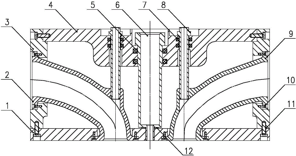
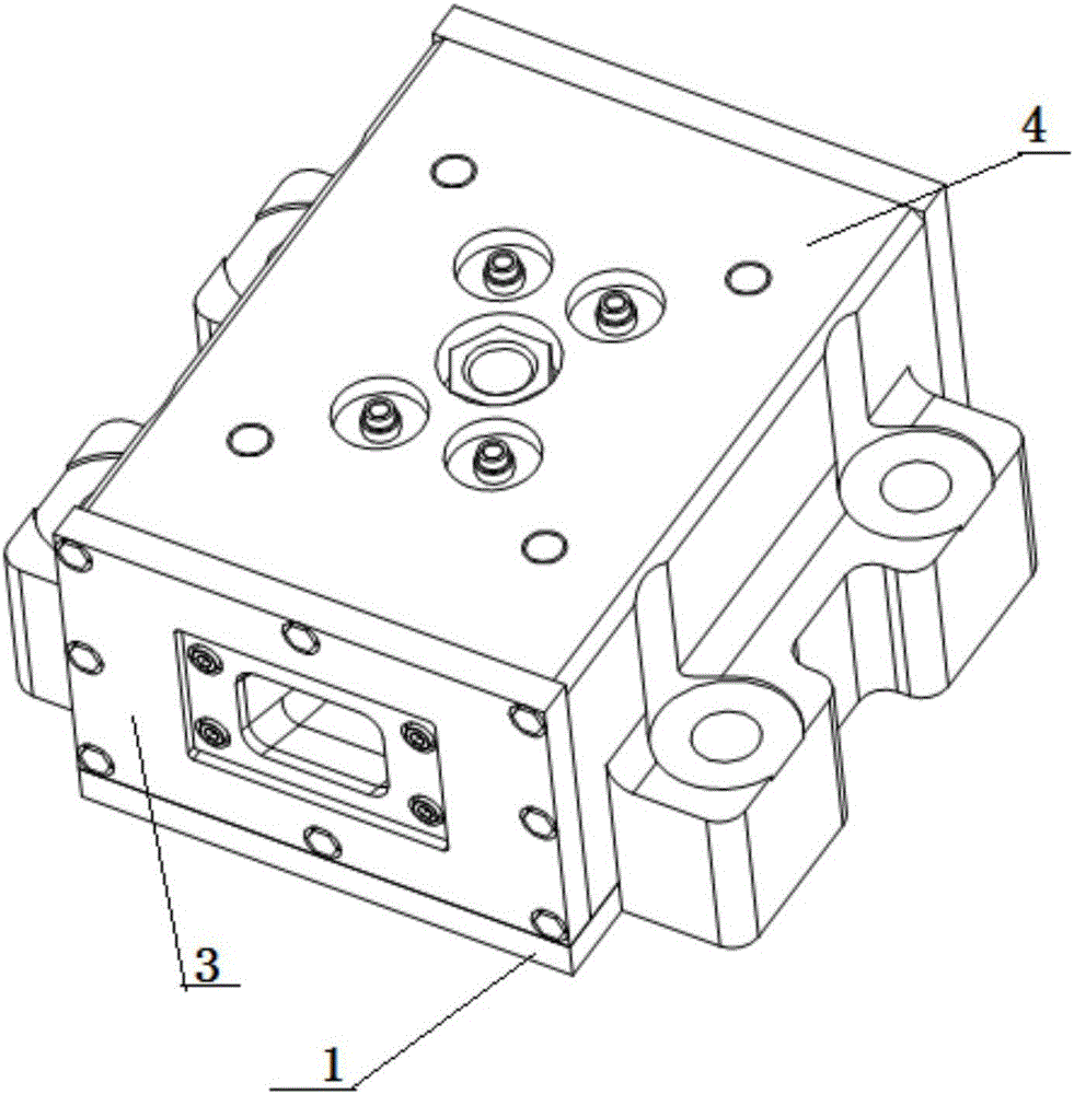
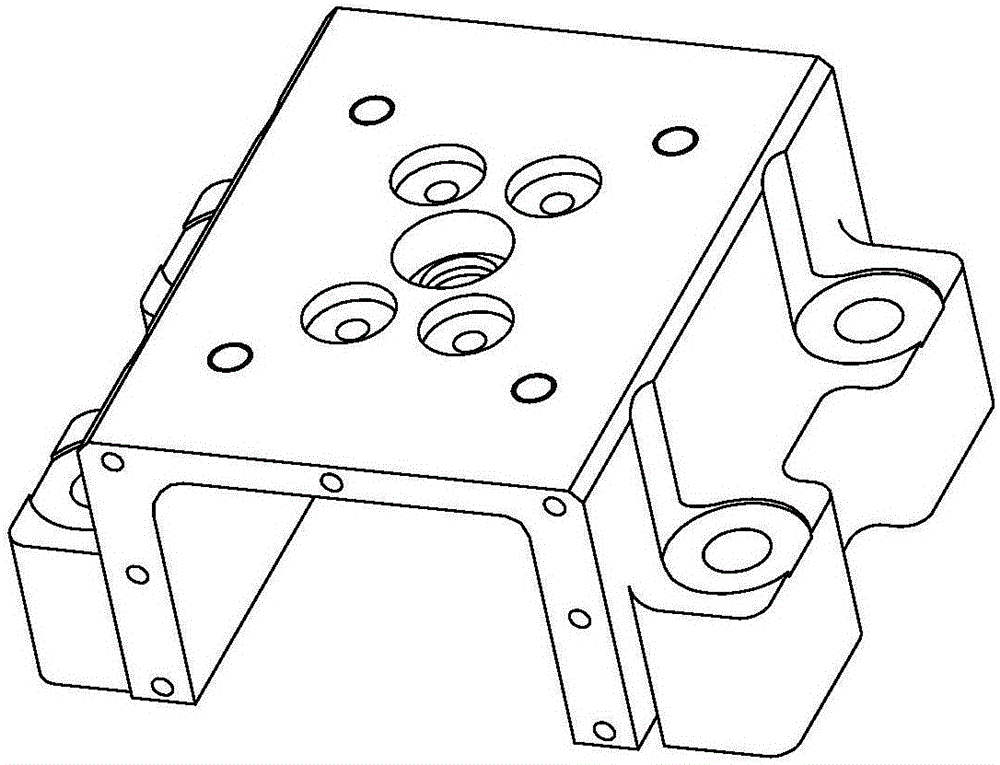
The invention provides a combined air cylinder cover. The combined air cylinder cover comprises an upper top plate, a plurality of side plates, a lower bottom plate, an air inlet channel movable block, an exhaust channel movable block, an oil atomizer lining and a plurality of guide pipes. A rectangular air cylinder cover structure is formed by the upper top plate, the side plates and the lower bottom plate. Each of the air inlet channel movable block and the exhaust channel movable block comprises a middle air channel and installing flanges at the two ends. One end of the air inlet channel movable block and one end of the exhaust channel movable block are connected with the two oppositely-arranged side plates through the installing flanges correspondingly, and the other end of the air inlet channel movable block and the other end of the exhaust channel movable block are both connected with the lower bottom plate. An integrally-cast cylinder cover is decomposed into the combined machining cylinder cover, the air inlet channel movable block and the exhaust channel movable block are arranged in a matched manner, air inlet channels and an exhaust channels, all of which are different in design parameter, can be conveniently replaced, and the link that the cylinder cover needs to be cast and machined again due to change of the design parameters of the air inlet channel and the exhaust channel is omitted.

Description

technical field [0001] The invention belongs to the field of engine performance tests, in particular to a combined cylinder head. Background technique [0002] As one of the key parts of the engine, the cylinder head bears the periodic force of bolt compression force, gas pressure and heat load during the working process. Continuously improving the structural strength of the cylinder head is the goal pursued by engine engineers. At the same time, different The comparison test of airway structure parameters is an important link in the process of engine performance research and development. Therefore, whether the intake and exhaust passages of different parameters can be replaced conveniently and quickly plays an important role in improving the efficiency of engine performance tests. Contents of the invention [0003] In view of this, the present invention aims to propose a combined cylinder head to solve the problem that the cylinder head is prone to damage during the engin...

Claims


Application Information

Patent Timeline
Patent Type & Authority Applications(China)
IPC IPC(8): F02F1/24F02F1/42G01M15/00
CPCF02F1/242F02F1/4214F02F1/4285F02F2001/244G01M15/00
Inventor 于波李玉峰王子玉吉建波张冬梅刘玮张晓琴
Owner CHINA NORTH ENGINE INST TIANJIN
Learn More