
Energy saving and emission reduction fuel saving device

An energy-saving, emission-reduction, and fuel-saving technology, which is applied in the charging system, combustion engine, combustion air/combustion-air treatment, etc., can solve the problem of difficult to promote full combustion of fuel, reduce the working reliability of the economizer, and shorten the use of the economizer. Life and other issues, to achieve the effect of simple structure, improve life, and promote complete combustion

Inactive Publication Date: 2018-11-20
张金庆
View PDF8 Cites 0 Cited by
  • Summary
  • Abstract
  • Description
  • Claims
  • Application Information

AI Technical Summary

Problems solved by technology

At present, the magnetized fuel saver is more popular. This kind of fuel saver is prone to magnetic flux leakage. The car components near the fuel saver are easily affected by the magnetic field and the fuel saver itself is easy to demagnetize, which shortens the service life of the fuel saver. , it is difficult to promote the full combustion of fuel, which greatly reduces the reliability of the fuel economizer

Method used


Image

  • Energy saving and emission reduction fuel saving device
  • Energy saving and emission reduction fuel saving device
  • Energy saving and emission reduction fuel saving device

Examples


Embodiment Construction

[0023] Embodiments of the present invention are described in detail below, examples of which are shown in the drawings, wherein the same or similar reference numerals designate the same or similar elements or elements having the same or similar functions throughout. The embodiments described below by referring to the figures are exemplary and are intended to explain the present invention and should not be construed as limiting the present invention.

[0024] As shown in the accompanying drawings, the present invention discloses an energy-saving, emission-reducing and fuel-saving device.

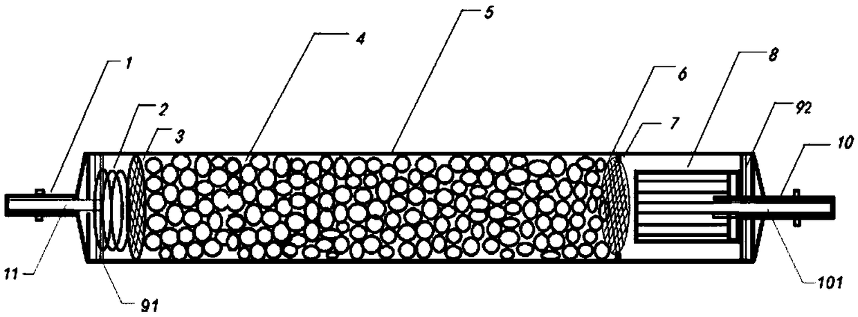
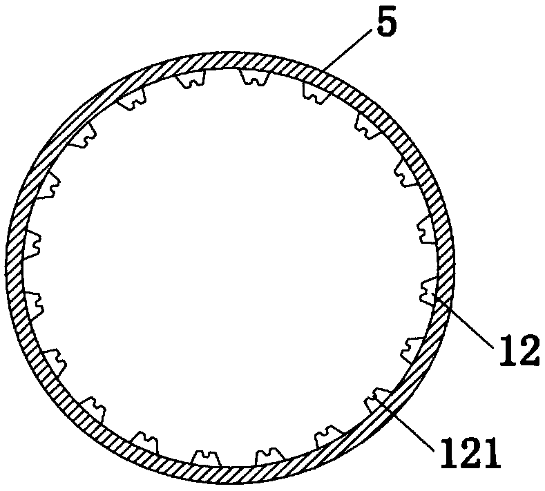
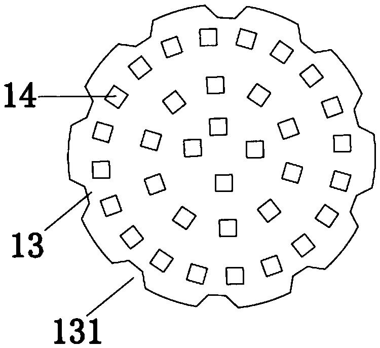
[0025] see figure 1 , the present invention includes an oil inlet side plug 1, a barrel body 5, an oil outlet side plug 10 and catalytic particles 4, the barrel body is a semi-closed cavity structure, and the oil inlet side plug 1 and the oil outlet side plug 10 are connected in a cavity shape The oil inlet side plug 1 and the oil outlet side plug 10 are respectively fixed on the two ends of...


PUM


Abstract

The invention provides an energy conservation and emission reduction fuel-saving device. The device comprises a barrel body. The two ends of the barrel body are provided with an inlet end and an outlet end correspondingly. A fuel inlet plug is mounted at the inlet end. A fuel outlet plug is mounted at the outlet end. The barrel body is provided with a cavity which is filled with catalyst particles. The two ends of the catalyst particles are fixed through a first grid close to the fuel inlet plug and a second grid close to the fuel outlet plug correspondingly. A first inner fuel pipe is arranged on the fuel inlet plug. A second inner fuel pipe is arranged on the fuel outlet plug. The extension sections of the first inner fuel pipe and the second inner fuel pipe both extend into the cavity. The energy conservation and emission reduction fuel-saving device is simple in structure. The catalyst particles are arranged in the barrel body to shatter and catalyze fuel, so that the fuel is burned completely, the fuel utilization rate is increased, and the purpose of fuel economization is achieved. The energy conservation and emission reduction fuel-saving device is simpler in structure. The service life of a whole fuel economizer cannot be affected by magnetization reaction. The high-temperature-resisting and anticorrosive barrel body and a high-temperature-resisting and anticorrosive oil seal are adopted, and the service life of the whole fuel economizer is further prolonged.

Description

technical field [0001] The invention relates to the technical field of energy-saving for diesel and gasoline vehicles, in particular to an energy-saving, emission-reducing and fuel-saving device. Background technique [0002] With the rapid development of the automobile industry and the improvement of people's living standards, our country has entered the era of automobiles, and the number of vehicles on the road is increasing, which brings two main problems: energy consumption and environmental pollution. At present, the energy situation in the world is becoming more and more serious. Fuel engines are the major players in carbon energy consumption and carbon emissions, and they are also the key targets of energy saving and emission reduction. How to improve the quality of fuel oil, improve the conversion rate of fuel oil, and reduce the exhaust gas emissions of fuel oil engines Today's society urgently needs to solve the problem. At present, the whole world is looking for a...

Claims


Application Information

Patent Timeline
Patent Type & Authority Patents(China)
IPC IPC(8): F02M27/02F02M37/22
CPCF02M27/02F02M37/22Y02T10/12
Inventor 张金庆
Owner 张金庆
Learn More