
Tubular-turbine hydro-generator

A hydroelectric generator, tubular technology, applied in the direction of hydroelectric power generation, reaction engine, engine components, etc., can solve the problem of unusable water turbine generator drop, to improve work utilization, save water, improve power generation The effect of power

Inactive Publication Date: 2016-10-26
ANHUI ZHUANGYUANLANG ELECTRONICS TECH
View PDF8 Cites 2 Cited by
  • Summary
  • Abstract
  • Description
  • Claims
  • Application Information

AI Technical Summary

Problems solved by technology

[0003] The technical problem to be solved by the present invention is to overcome the defects that existing hydraulic generators cannot be used in many places with small water flow and small drop, and to provide a tubular hydraulic generator

Method used


Image

  • Tubular-turbine hydro-generator

Examples


Embodiment 1

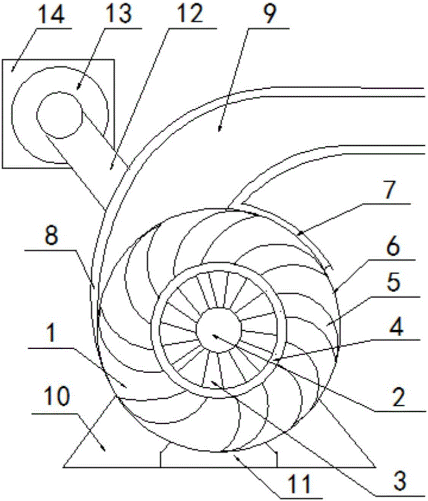
[0014] Such as figure 1 As shown, the present invention provides a tubular hydroelectric generator, comprising a hydro turbine body 1, a rotating shaft 2, a connecting rod 3, a drum 4, blades 5, a water sealing plate 6, a lower water retaining plate 7, and an upper water retaining plate 8. The water inlet 9, the base 10, the water outlet 11, the transmission mechanism 12, the generator body 13 and the sealing sleeve 14, the inside of the turbine body 1 is provided with a rotating shaft 2, and the outer surface of the rotating shaft 2 is connected with several connecting rods 3, and the rotating cylinder 4 The connecting rod 3 is connected with the rotating shaft 2, and the outer surface of the drum 4 is connected with a plurality of blades 5, and the periphery of the plurality of blades 5 is provided with a water sealing plate 6, and a water inlet 9 is provided above the water turbine body 1, and a water inlet 9 is provided above the water inlet 9. The upper water deflector 8,...


PUM


Abstract

The invention discloses a tubular-turbine hydro-generator which comprises a turbine body, a rotating shaft, a plurality of connecting rods, a rotating drum, a plurality of vanes, a water sealing plate, a lower water baffle, an upper water baffle, a water inlet, a base, a water outlet, a transmission mechanism, an engine body and a sealing sleeve, wherein the rotating shaft is arranged in the turbine body; the outer surface of the rotating shaft is connected with connecting rods; the rotating drum is connected with the rotating shaft through the connecting rods; the outer surface of the rotating drum is connected with the vanes; the water sealing plate is arranged at the peripheries of the vanes; the water inlet is formed above the turbine body; the upper water baffle is arranged above the water inlet; the lower water baffle is arranged below the water inlet; the base is arranged below turbine body; the water outlet is formed in the base; the engine body is connected with the rotating shaft through the transmission mechanism; the transmission mechanism comprises a transmission shaft and a shaft sleeve; and the sealing sleeve is arranged at the exterior of the engine body. With the adoption of the tubular-turbine hydro-generator, turbine power generation requires no high water flow or high water level difference, and energy conservation and environmental protection are facilitated better.

Description

technical field [0001] The invention relates to a hydraulic generator, in particular to a tubular hydraulic generator, which belongs to the field of hydraulic power generation equipment. Background technique [0002] Hydropower generation requires the use of water turbines to convert the impact of water flow into power for generators, which is an environmentally friendly and clean way to obtain electricity. The current water turbine works like this. The water turbine is composed of a casing and a rotatable impeller in the casing. The blades are arranged in a straight line and vertically distributed on the cylindrical surface of the impeller. The water turbine is installed at the lower part of the embankment. And the water flow impacts the impeller, which makes the impeller rotate and drives the generator to generate electricity. Such technology has the following disadvantages: there must be a large water flow rate and a fast flow rate to provide the impact force to push the...

Claims


Application Information

Patent Timeline
IPC IPC(8): F03B13/00F03B3/12F03B3/16
CPCF03B3/12F03B3/16F03B13/00Y02E10/20
Inventor 蒋智谋胡加峰李敬龙蒋加佳朱文峰刘帅
Owner ANHUI ZHUANGYUANLANG ELECTRONICS TECH
Learn More