Radiant Tube Heating

A technology of tubular heating and radiant tubes, which is applied in the direction of lighting and heating equipment, burners, combustion types, etc., can solve the problems of thermal efficiency improvement limitations, environmental hazards, etc., and achieve the effect of suppressing local rise and suppressing generation

Active Publication Date: 2019-04-26
DAIDO STEEL CO LTD
View PDF6 Cites 0 Cited by
  • Summary
  • Abstract
  • Description
  • Claims
  • Application Information

AI Technical Summary

Problems solved by technology

[0003] However, in the case of preheating the combustion air by using the heat of the exhaust gas as in the above-mentioned radiant tube type heating device, there is a problem that since the nitrogen in the combustion air is oxidized as the combustion temperature in the burner rises, As a result, nitrogen oxides such as nitrogen monoxide or nitrogen dioxide (NO x )
As a result, since the preheating temperature is limited by the limit value, the improvement of thermal efficiency is limited

Method used


Image

  • Radiant Tube Heating
  • Radiant Tube Heating
  • Radiant Tube Heating

Examples


Embodiment Construction

[0066] Next, modes for carrying out the present invention will be described.

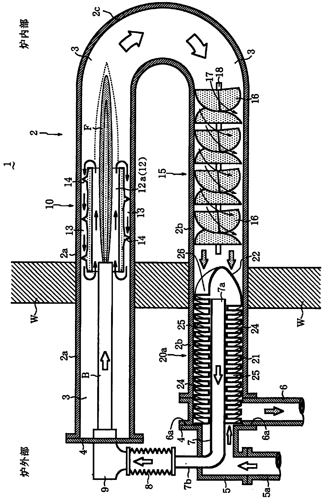
[0067] figure 1 is a vertical sectional view showing the radiant tube heating device 1 according to the embodiment of the present invention. The radiant tube heating device 1 corresponds to the third radiant tube heating device described above.

[0068] Such as figure 1 As shown, the radiant tube heating device 1 includes: a tubular radiant tube 2, which passes through the furnace wall (furnace body) W horizontally along the inner and outer directions; a burner B, which is coaxially arranged on one end side of the radiant tube 2 In the central portion of the hollow portion 3 of the radiant tube 2; the temperature rise suppressing member 10 arranged in the hollow portion 3 at a position surrounding the opening portion on the tip side of the burner B; and the heat radiation member 15 and the heat exchanger 20a , which are successively arranged in the hollow portion 3 on the other end side of the ra...


PUM


Abstract

The present invention provides a radiant tube heating device capable of achieving at least one or both of suppressing generation of nitrogen oxides (NOx) generated by a combustor and remarkably improving thermal efficiency. The radiant tube heating device(1) comprises a radiant tube (2) having its two ends (2a, 2b) penetrating the furnace wall (furnace) (W), and the bent portion (2c) Protruding into the interior of the furnace;and a burner (B) arranged coaxially in the hollow portion (3) in the central portion of the hollow portion (3) on one end (2a) side of the radiation tube (2); the radiant tube heater (1) further includes a temperature rise suppressing member (10) having a cylindrical shape and arranged at a position around an opening portion on the distal end side of the combustor in a hollow portion of the radiant tube , and a pair of inner and outer flow paths (12a, 13) for flowing combustible gas are formed between the inner wall surface of the radiant tube and the outer peripheral surface of the burner.

Description

technical field [0001] The present invention relates to radiant tube heating devices for heating an atmosphere, eg in a heat treatment furnace, while keeping the atmosphere clean. Background technique [0002] In general, radiant tube heating is required to efficiently raise the temperature of the combustion air, thereby improving overall thermal efficiency. For example, there has been proposed a radiant tube type heating device in which a burner is arranged on one end of the radiant tube, and heat is transferred from the other end of the radiant tube by circulating in a spiral heat exchanger installed on the outer peripheral side of the burner. The discharged exhaust gas preheats the combustion air supplied to the combustor within a desired temperature range (for example, refer to Patent Document 1). [0003] However, in the case of preheating the combustion air by using the heat of the exhaust gas as in the above-mentioned radiant tube type heating device, there is a prob...

Claims


Application Information

Patent Timeline
Patent Type & Authority Patents(China)
IPC IPC(8): F23D14/02F23D14/12F23D14/46F23D14/66
CPCF23D14/02F23D14/12F23D14/46F23D14/66F23D2203/005F23D2900/1412Y02E20/34
Inventor 伊藤英树神谷祐树托马斯·D·布里塞尔顿
Owner DAIDO STEEL CO LTD
Why Eureka
Try Eureka