Eureka AIR delivers breakthrough ideas for toughest innovation challenges, trusted by R&D personnel around the world.

Space-based kinetic energy weapon regressive orbit deployment method for regional striking task

A technology for returning to orbit and tasks, applied in the direction of weapon accessories, weapon types, instruments, etc., to achieve the effect of reducing the total number of platforms

Active Publication Date: 2016-10-26
NORTHWESTERN POLYTECHNICAL UNIV
View PDF6 Cites 2 Cited by
  • Summary
  • Abstract
  • Description
  • Claims
  • Application Information

AI Technical Summary

Problems solved by technology

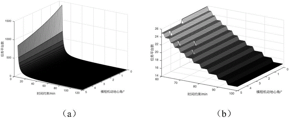
[0004] However, in terms of orbital deployment methods, the existing orbital deployment methods generally adopt the walker constellation deployment method, but this method is only suitable for the lift-type re-entry strike mode with strong maneuverability, and for kinetic strike weapons with low maneuverability Orbital deployment method, the design result of this method often requires thousands of platforms, such a large number of platforms is unacceptable in engineering practice

Method used


Image

  • Space-based kinetic energy weapon regressive orbit deployment method for regional striking task
  • Space-based kinetic energy weapon regressive orbit deployment method for regional striking task
  • Space-based kinetic energy weapon regressive orbit deployment method for regional striking task

Examples


Embodiment

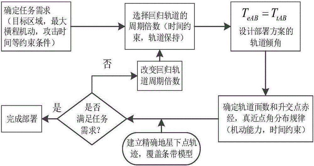
[0054] Using the regression orbit can make full use of the regression characteristics of the orbit to greatly reduce the demand for the number of platforms to meet the coverage of key areas. This will be verified and analyzed in conjunction with specific examples below.

[0055] Initial parameter setting:

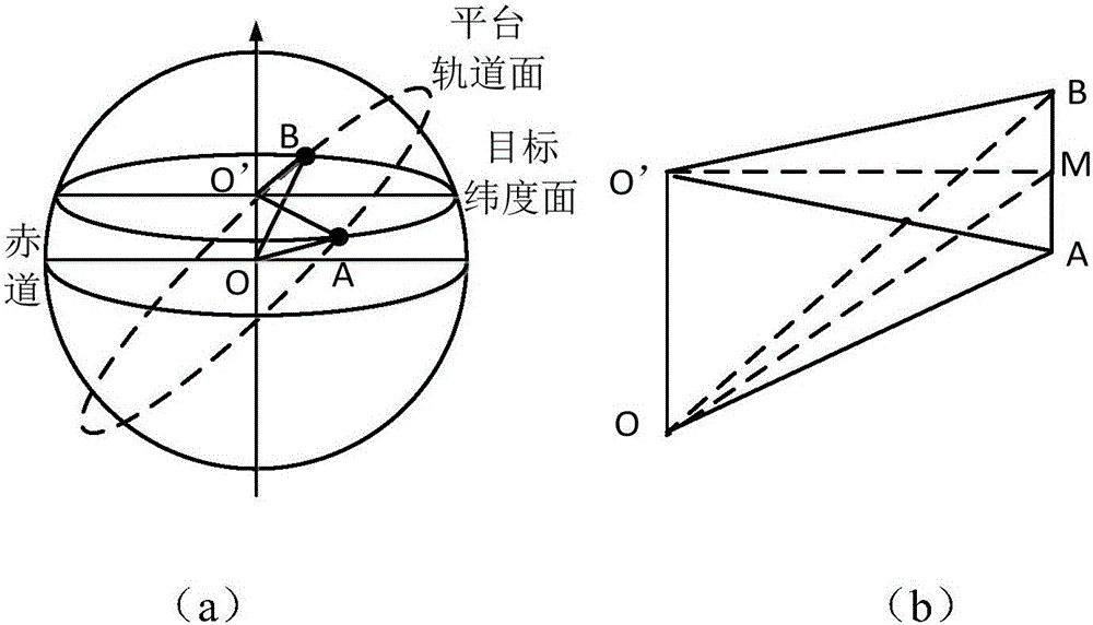
[0056] The kinetic energy weapon is a tungsten rod with a lift-to-drag ratio of 0.1, a length of about 6m, a diameter of 30cm, and a weight of about 100kg. It can be released from a space-based weapon platform according to instructions. The coverage area is approximately a circular area with a diameter of about 100km, and the corresponding lateral maneuver geocentric angle is about 1°; assuming that the longitude and latitude of the target area are 13.26N, 144E.

[0057] Deployment scheme design:

[0058] In the simulation, the return orbit with a period of 1 / 16 of the earth's rotation period is selected, and 9 platforms with n=6 orbital inclination angles of 36.92° are se...

Embodiment

[0059] Implementation example analysis:

[0060] Figure 6 and Table 4 are related charts of STK simulation scene coverage performance, Figure 6 It is the time axis for the coverage of the target area within 24 hours from 12:00 on June 1, 2007 to 12:00 on June 2, 2007, and Table 4 is for Figure 6 specific data list. Depend on Figure 6 It can be seen from Table 4 that the time interval between every two coverages meets the task requirements.

[0061] Figure 7 and Figure 8 It is the 3D rendering of the return orbit deployment method and the 2D rendering of the sub-satellite point trajectory. Figure 9 Several representative key moments within 24 hours after the start of the simulation are given, in which the colored area in the figure is the target area of ​​the mission, and the cyan cone is the schematic diagram of the reachable area of ​​the platform's ground coverage. Figure 9 (a) is the moment when weapon platform 1 completes the strike mission during the uplink p...


PUM

PropertyMeasurementUnit
Diameteraaaaaaaaaa

Abstract

The invention discloses a space-based kinetic energy weapon regressive orbit deployment method for a regional striking task. According to the space-based kinetic energy weapon regressive orbit deployment method for the regional striking task, the rapid striking task can be completed on the same task background only through nine platforms. By means of the orbit characteristic that a sub-satellite point track returns to an original passing path again a certain period of time later through the regression effect brought by the special relation between the regressive orbit cycle and the earth rotation cycle, an orbit deployment way of space-based kinetic energy weapons for the regional striking task in a single orbit plane can be achieved only through one platform, and thus the total number of platforms required by the task is greatly reduced.

Description

【Technical field】 [0001] The invention relates to a space-based kinetic energy weapon return-to-orbit deployment method for regional strike missions. 【Background technique】 [0002] As early as the 1980s, under the background of "Star Wars", the U.S. military had a preliminary idea of ​​developing the "Stand of God", which means throwing kinetic energy rods made of tungsten, titanium and other metals from space-based platforms to destroy the ground. Target. Recently, the United States once again proposed the space-based kinetic energy rod ground strike weapon plan, and plans to complete the deployment in 2025 and initially form combat effectiveness. Other conventional weapons often do not have strategic deterrent capabilities, and conventional weapons are often helpless against important and deeply buried targets that are becoming more and more solid. The above multiple factors have prompted the U.S. military to seek new breakthroughs and new strategic commanding heights i...

Claims


Application Information

Patent Timeline
IPC IPC(8): F41B15/00F41G9/00G06F19/00
CPCF41B15/00F41G9/00G16Z99/00
Inventor 罗建军姚玮袁建平朱战霞马卫华唐歌实胡松杰李革非
Owner NORTHWESTERN POLYTECHNICAL UNIV
Why Eureka
Eureka Blog
Learn More