
Protecting method of optical-fiber grating sensor attached to surface of composite-material structure

A composite material, fiber grating technology, applied in the direction of optical testing flaws/defects, can solve the problems of affecting the structural performance of composite materials, cumbersome operation, reducing periodic inspections, etc., to avoid personnel safety accidents and economic losses, and the process is simple. , Reduce the effect of periodic inspection

Active Publication Date: 2016-10-26
BEIJING CHANGCHENG INST OF METROLOGY & MEASUREMENT AVIATION IND CORP OF CHINA
View PDF7 Cites 3 Cited by
  • Summary
  • Abstract
  • Description
  • Claims
  • Application Information

AI Technical Summary

Problems solved by technology

[0004] The purpose of the present invention is to solve the problem that internal defects will be introduced when the fiber grating sensor is embedded in the composite material for structural health monitoring, which will affect the structural performance of the composite material itself. On the one hand, in order to solve the problems that when the fiber grating sensor is installed on the surface of the composite material structure with the traditional adhesive, the adhesive has poor anti-aging performance, the installation process is difficult to control, the operation is cumbersome, and it is easy to be damaged when the environment is harsh. The fiber grating sensor protection method realizes the close combination and protection of the fiber grating sensor and the composite material structure, and can also monitor the health status of the composite material structure in real time, reducing scheduled weekly inspections, and maintaining according to the monitoring results, reducing manpower. , financial and material input, and at the same time avoid personnel safety accidents and economic losses caused by structural failures

Method used


Image

  • Protecting method of optical-fiber grating sensor attached to surface of composite-material structure
  • Protecting method of optical-fiber grating sensor attached to surface of composite-material structure
  • Protecting method of optical-fiber grating sensor attached to surface of composite-material structure

Examples


Embodiment Construction

[0026] The present invention will be described in detail below in conjunction with the accompanying drawings.

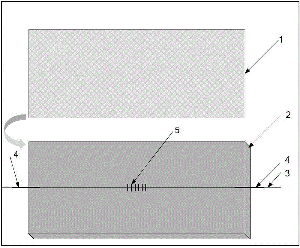
[0027] refer to figure 1 , a surface-attached fiber grating sensor protection method for a composite material structure, the specific implementation steps are as follows:

[0028] 1. Fix the composite material laminate 2 horizontally on the workbench;

[0029] 2. Cover both ends of the fiber grating sensor 5 with a protective sleeve 4, and place it on the surface of the composite laminate 2. The sleeve extends into the end face of the composite laminate 2 by 10 mm, and connects the optical fiber and the sleeve with quick-drying glue Fix at the place, and evenly apply 0.5mm thick adhesive on the surface of the laminate to fix the optical fiber 3 and the protective sleeve 4;

[0030] 3. Lay the glass fiber cloth 1 neatly on the adhesive, install a putty strip around the fiber cloth, fix the special film for vacuuming with the putty strip, and use a vacuum device to v...


PUM

PropertyMeasurementUnit
thermal resistanceaaaaaaaaaa

Abstract

The invention relates to a protecting method an optical-fiber grating sensor and belongs to the technical field of optical fiber sensing and structure health monitoring. The protecting method includes: fixing a composite-material laminated board (2) to a workbench; sleeving protective sleeves (4) at two ends of the optical-fiber grating sensor (5), placing the optical-fiber grating sensor (5) on the surface of the composite-material laminated board, allowing the sleeves to extend into the end face of the composite-material laminated board at a certain distance, using quick-drying glue to fix optical fibers and the sleeves, and evenly coating the surface of the composite-material laminated board with adhesive mu mm in thickness to fix the optical fibers (3) and the protective sleeves; neatly laying glass fiber cloth on the adhesive, mounting putty strips on the periphery of the fiber cloth, fixing a thin film special for vacuumizing with the putty strips, and vacuumizing the whole glass fiber cloth surface with a vacuumizing device under normal temperature until the relative vacuum degree reaches -0.1MPa; curing the whole structure for gamma hours under normal temperature. Compared with the prior art, the protecting method has the advantages that the method is simple in process flow and little in influence on the mechanical performance and assembling of composite-material structural components.

Description

technical field [0001] The invention relates to a method for protecting an optical fiber grating sensor surface-mounted on a composite material structure, and belongs to the technical field of optical fiber sensing and structural health monitoring. Background technique [0002] With the continuous development of fiber optic sensor technology, fiber grating sensors are more and more widely used in engineering measurement. Compared with traditional sensors, it has many advantages of its own, such as small size, small energy loss during transmission, wavelength division multiplexing and distributed sensing, high temperature resistance, corrosion resistance, no electromagnetic interference, and can work in harsh environments Wait. [0003] Due to the small size of the fiber sensor (155 μm), it is easy to embed in the composite material. In recent years, the fiber grating sensor has been gradually used in the health detection of composite material structures and the field of int...

Claims


Application Information

Patent Timeline
Patent Type & Authority Applications(China)
IPC IPC(8): G01N21/88
CPCG01N21/88
Inventor 王文娟宋昊薛景锋
Owner BEIJING CHANGCHENG INST OF METROLOGY & MEASUREMENT AVIATION IND CORP OF CHINA
Learn More